Fixture Design for Wire-to-PCB Robotic Soldering: How to Improve Positioning and Repeatability
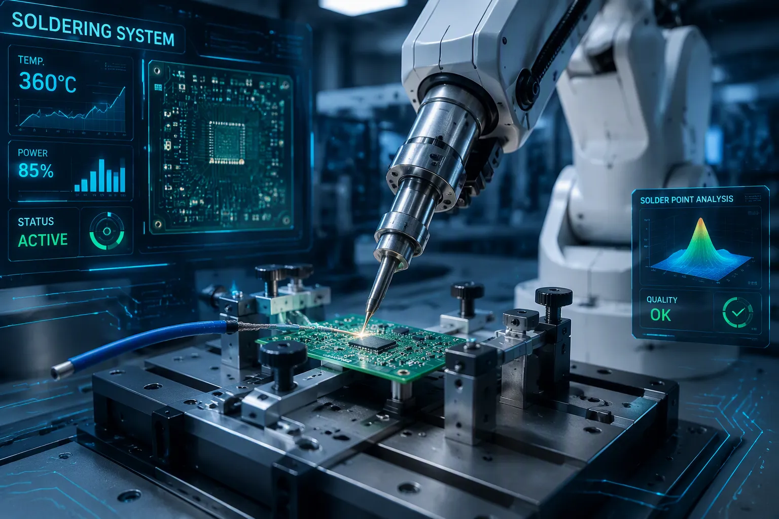
You know the frustration. A wire moves just a tiny bit. The PCB shifts slightly from heat. Your robotic soldering station makes a bad joint. Fixing it costs time and money. Scrap piles up.
Good fixture design for wire-to-PCB robotic soldering fixes these issues. Your fixture holds every part tightly. It gives steady reference points. This accuracy keeps results the same over thousands of cycles. Without solid fixturing, even the best robot fails.
This guide gives practical, engineering-focused answers. You will see how positioning, repeatability, and heat control connect. You will find material choices that keep performance high. You will learn methods for automated soldering success. Proper fixturing turns your soldering work from frustrating to flawless. Trust automation with confidence. Your output will grow. Your defects will drop.
Key Takeaways
Use solid holders with set guide marks to keep parts in place.
Use materials such as aluminum, which do not expand much when heated.
Design wire guides and clamps that hold wires firmly.
Use locating pins to place the PCB quickly and correctly.
Test your fixture under real heat to make sure you get the same results every time.
Core Challenges in Fixture Design for Wire-to-PCB Robotic Soldering
Wire Alignment and PCB Stability
A bendable wire and a stiff PCB act very differently. The wire can bend, twist, or pop out of place. The PCB stays fixed. This difference causes alignment errors that hurt the solder joint quality. Putting wires in by hand adds more variation. Each worker puts the wire in a slightly different spot. This gives you inconsistent soldering. It also changes the soldering tip's position compared to the joint. Custom fixtures fix this. They lock the wire in a set path. They hold the PCB tight with clamps or suction. Good alignment starts by knowing how these two parts act. Your fixture must connect the bendable wire and the stiff PCB.
Thermal Effects and Material Deformation
Heat from the soldering iron changes the shape of your fixture and parts. Materials get bigger when they heat up. How much they grow depends on the material's thermal expansion number. This growth causes the position to drift. A tiny shift in position can ruin the solder joint. Over many cycles, these heat effects kill repeatability.

Engineering plastics grow a lot more than metals. Acetal's thermal expansion number is about 0.000068 in/in/°F. That is over three times aluminum's number of 0.000013 in/in/°F. Even PEEK, a more stable plastic, grows at about double the rate of aluminum. Good fixturing needs careful material choice. A plastic fixture that holds a wire near the soldering point moves more as it heats up. An aluminum fixture keeps its shape better. The chart above shows the differences clearly. Stainless steel grows the least. Acrylic and ABS grow the most. Picking the right material directly affects your system's accuracy and performance.
You must plan for thermal growth in your fixture design for wire-to-PCB robotic soldering. A fixture that works well at room temperature may drift out of spec during production. This is a hidden cause of poor repeatability. Plan for heat. Use materials with low thermal growth near the soldering zone. This keeps your automated soldering steady cycle after cycle. Without good fixturing, heat drift ruins consistency.
Key Principles for Ensuring Repeatability in Robotic Soldering
Rigidity and Datum Features
A datum gives you a fixed starting point. You pick one spot on the PCB as your reference. Every wire placement uses that same spot. The soldering tool also lines up to that datum. This system makes sure each joint forms in the exact same place. Without a datum, you depend on guesswork. Each part lands a bit differently. Your soldering results change.
Rigidity supports your datum system. A flexible fixture bends under pressure. It moves during the soldering cycle. These shifts ruin positional accuracy. You need a stiff structure that resists bending. Metal plates and reinforced ribs keep everything locked in place. Your fixture must hold the PCB and wire firmly. Any looseness in the system leads directly to bad joints.
Think of your fixture as the backbone of the operation. It passes the robot's precision to the workpiece. A rigid frame with clear datum features gives you steady quality. You can trust that cycle 500 matches cycle 5. This consistency builds the base for successful automated soldering.
Material Selection for Thermal Stability
Heat changes your fixture's shape. Different materials react differently. Aluminum expands at 0.000013 in/in/°F. Acetal grows at 0.000068 in/in/°F. That difference matters near the soldering tip. A plastic fixture drifts more as it heats. An aluminum fixture holds its position better.
Steel offers even more stability. It expands less than aluminum. But steel weighs more and costs more. You must balance stability against practical needs. Aluminum often gives the best mix. It resists heat deformation well. It stays lightweight. It machines easily.
Engineered plastics have their place. They work for low-temperature zones. They suit areas far from the soldering tip. But keep them away from direct heat. Their expansion will ruin your accuracy. Choose your materials based on how close they sit to heat sources. This choice directly affects your long-term performance.
Your fixture design for wire-to-pcb robotic soldering must plan for thermal growth. A fixture that works at room temperature may fail during production. Plan for heat from the start. Select materials that keep their shape. This method ensures steady soldering across thousands of cycles. Your fixturing investment pays off through fewer defects and less rework.
Step-by-Step Guide to Designing a Soldering Fixture
Start with the PCB. Your board needs a secure base before you handle the wire. Edge clamps work well for most jobs. They grip the board's edges without blocking access to solder joints. Vacuum fixtures offer another choice. They hold the board flat with suction. This method works best for thin or flexible PCBs that might bend under clamp pressure. Pick your approach based on your board's stiffness and where your solder points sit.
The wire brings a different challenge. You need channels or guides that push the wire into the right position. These guides should match the wire's path from its entry point to the solder joint. A simple V-groove works for many cases. It centers the wire while making loading easy. For more complex setups, try a closed channel with a removable cover. This design holds the wire firmly along its full length.
Your fixture design for wire-to-pcb robotic soldering must handle wire thickness changes. Manufacturing tolerances mean your wire diameter shifts slightly from spool to spool. Spring-loaded clamps solve this problem neatly. These clamps use a constant-force internal spring. As the conductor diameter varies, the spring adjusts its grip on its own. This dynamic adjustment keeps clamping pressure steady. Your wire stays firmly in place even under vibration or temperature changes. The spring mechanism keeps contact quality throughout the soldering cycle.
PCB Clamping and Wire Management
Place your clamping points carefully. Avoid areas where the soldering tip needs room. Put clamps at least 0.25 inches from any solder joint. This distance stops the clamp from blocking the robot's movement path. For boards with parts on both sides, use edge clamps only. They grip just the board's edges and leave both surfaces open.
Wire management needs attention to entry angles. The wire should reach the solder joint at the same angle every cycle. A wire guide that bends the wire too sharply creates stress. This stress can make the wire spring back during soldering. Design your guides with wide radii. A bend radius of at least three times the wire diameter stops kinking and keeps feeding smooth.
Integrating Alignment Features and Locating Pins
Locating pins give you fast, accurate PCB placement. Two pins create a solid reference system. Put one pin in a round hole and the second in a slotted hole. This setup stops over-constraint while keeping positioning steady. The round pin fixes the board's X and Y position. The slotted pin allows for thermal expansion without sticking.
Spring-loaded locators add another layer of precision. These devices adjust on their own to the size of the workpiece. They keep a secure hold while making up for small changes in part sizes. Your positional reference point stays constant even when incoming parts vary. This self-adjusting system proves useful in high-volume production.
These precision alignment fixtures cut changeover time a lot. You can swap PCBs quickly without manual alignment. The locating pins make sure every board sits in the same spot. Your robotic soldering system then gives consistent joint quality across every cycle.
Good fixturing designs combine all these parts. Rigid clamping, guided wire paths, and precise locating pins work together. This combined approach delivers the repeatability you need for automated soldering success. Your soldering results stay consistent through thousands of cycles. Defects drop. Throughput rises. Your investment in careful fixture design pays off right away.
Advanced Techniques for Enhancing Automated Soldering Repeatability
Your basic fixture handles the main problems. Advanced methods push your system further. These techniques cut changeover time, fix heat drift, and check that your process stays accurate over thousands of cycles. You move from good soldering to great soldering.
Modular Designs and In-Process Correction
Modular fixtures change how you handle production flexibility. You build a base plate that stays on the robot. Then you attach different inserts for each PCB or wire type. Swapping an insert takes minutes, not hours. You do not re-align the whole system. The base plate holds the datum features. Each insert locks into the same spot. This design cuts changeover time a lot. You run small batches profitably. You switch between products without losing precision.
In-process correction tools fix problems that show up during production. The soldering tip expands as it heats. It also wears down over time. Both issues shift the tip's position. A tip position corrector fixes this problem on its own. It adjusts tip slippage from heat expansion, burning out, or other causes. It runs fully automated without needing reset conditions or reconfiguration. This ensures steady quality by handling unexpected slippage. You do not stop the line to fix drift. The system corrects itself.
Intelligent solder feeders add another layer of control. These devices manage wire feed with precision. Consider the FU-500 intelligent solder feeder. It brings several key improvements:
Lock-on mechanism: Holds wire solder feed in a fixed spot, avoiding defects from feed misalignment.
Precision feed control: Ranges from 0.015 mm to 0.072 mm per pulse, allowing accurate solder volume management.
5-phase stepper motor with encoder-based error detection: Ensures smooth wire feeding and spots wire slippage or feeding stops, preventing inconsistent joints.
The table below shows how specific features improve your results:
Feature | How it improves repeatability |
|---|---|
FU-500 intelligent solder feeder | Automatically feeds solder wire to a specific position; allows easy adjustment of feed position, critical for automated systems. |
Compact driver unit | Brings feed closer to the iron, increasing accuracy of the amount of solder fed. |
Optical sensor | Detects solder clogging, slipping, and end of roll, preventing inconsistent joints. |
Tip alignment tool | Enables quick replacement and realignment of tips, ensuring consistent soldering geometry. |
These tools work alongside your fixture design for wire-to-pcb robotic soldering. They fix variables your fixture cannot control. Together, they deliver the consistency you need for high-quality automated soldering.
Validating the Automated Soldering Process
Your fixture and tools only form part of the solution. You must prove the whole system works together. Process validation confirms that your fixture, robot, and soldering settings keep positional accuracy over many cycles. Without validation, you guess. Guessing leads to surprises on the production floor.
Start with a pilot run. Run at least 100 cycles with your production parts. Measure the solder joint quality at regular intervals. Check the wire position and PCB alignment after each batch. Record any drift you see. This data tells you whether your fixturing holds up under real conditions.
Next, test for thermal stability. Run the system continuously for an hour. Measure joint positions at the start, middle, and end. Compare the measurements. If you see drift, examine your fixture materials and clamping points. You may need to add heat shielding or switch to a more stable material near the soldering zone.
Finally, document your results. Create a standard operating procedure that includes the validation data. This record helps you troubleshoot future problems. It also gives you confidence when scaling production. Your robotic soldering system becomes a reliable partner. You trust it to produce consistent joints hour after hour.
These advanced techniques transform your operation. Modular fixtures reduce downtime. In-process correction handles heat and wear. Validation proves your system works. You achieve the repeatability that makes automation solutions worthwhile. Your investment in fixturing and process control pays off through fewer defects, less rework, and higher throughput. You build a soldering operation that performs flawlessly, cycle after cycle.
Your fixture forms the foundation of successful robotic soldering. It directly impacts quality and productivity. Three principles guide your design. Prioritize rigidity and datum features. Choose materials wisely for thermal management. Follow a systematic design process.
View fixture design as a smart investment. It pays off through reduced scrap, less rework, and higher throughput. Good fixturing cuts costs over time. It makes your automated soldering consistent and reliable.
Integrate modularity and in-process correction. These features future-proof your robotic soldering operations. They handle heat drift and tip wear automatically. They reduce changeover time between products. Your automation solutions become more flexible and efficient. Soldering results stay steady through thousands of cycles.
FAQ
What is the most common mistake in fixture design?
The biggest mistake is ignoring thermal expansion. Engineers often make a fixture that works fine at room temperature. But production heat makes parts move. Pick materials that expand very little near the soldering area. Aluminum is a good choice. Always test your fixture under real heat before you start full production.
How do I know if my fixture has thermal drift?
To check for thermal drift, run your system for one hour non-stop. Measure where the joints are at the beginning, middle, and end. Compare those numbers. If you see any shift, your fixture is expanding from heat. Then use a material that changes less, or add a heat shield near the soldering tip.
Can I use 3D-printed plastic fixtures?
Yes, but only in places that stay cool. Plastics like ABS and acrylic grow three to five times more than aluminum when heated. Do not put them near the soldering tip. Use them for wire guides or covers. Use metal fixtures for spots that get direct heat.
How often should I validate my fixture setup?
First, run a test with at least 100 cycles using real parts. Check the joint quality at set times. After that, re-check whenever you change the wire type, PCB design, or soldering settings. Doing this regular check catches movement before it makes bad parts.
What is the best way to handle wire thickness variation?
Use spring-loaded clamps. They adjust on their own to small changes in wire size. They keep steady pressure without you needing to adjust them by hand. This holds the wire tight during the whole soldering cycle. Your fixture stays reliable even when the wire size changes a little.
See Also
Effective Techniques For Double-Sided Reflow In PCB Assembly
Top Strategies To Enhance SMT Line Efficiency In PCB Production
Key Considerations For SMT Assembly Of Rigid-Flex Circuit Boards
Ways To Optimize Hardware Assembly For Improved Outcomes
Essential Technical Tips For Wave Soldering In SMT Processes
