Reflow Soldering Process: Temperature Profile Optimization
To improve the temperature profile in the reflow soldering process, it's essential to ensure strong and reliable solder joints. Excessive temperature fluctuations can lead to thermal stress, which may result in cracks or brittle intermetallic layers. Implementing precise temperature control during the reflow soldering process helps prevent defects such as non-wetting or de-wetting. Effective reflow soldering enhances overall reliability and reduces the risk of long-term failures on your PCB. Since every assembly is unique, it's important to apply the appropriate method tailored to your specific situation.
Key Takeaways
Make the temperature profile better to get strong solder joints and fewer mistakes. This makes your PCB assemblies work well for a long time.
Use industry rules like IPC-7530 to set the right reflow profile. This stops common soldering problems and makes the quality better.
Check and adjust your reflow oven often. Keeping the temperature steady is important for even soldering results.
Use thermal profiling tools to watch the reflow process. This lets you change things right away and find problems early.
Always look at your PCB and parts before setting the profile. Every board is different, and knowing its details helps you get the best soldering.
Reflow Soldering Process Overview
What Is Reflow Soldering?
Reflow soldering helps connect electronic parts to a pcb. This process uses heat to melt solder paste. The melted paste makes strong connections. Reflow soldering is used a lot in making electronics today. You can find it in things like smartphones and laptops. It is also used in cars, medical tools, planes, and factories.
Consumer Electronics: Smartphones, tablets, laptops, wearables, home appliances
Automotive Electronics: ADAS, infotainment, engine control units
Medical Devices: Implantable and life-critical devices
Aerospace and Defense: Extreme reliability, special alloys
Industrial Electronics: Power modules, motor drives, control systems
People often look at reflow soldering and wave soldering to see how they are different. The table below shows how they are not the same:
Aspect | Reflow Soldering | Wave Soldering |
|---|---|---|
Defect Profiles | Tombstoning, solder balls, cold joints | Bridging, insufficient hole fill |
Common Issues | Thermal profile errors, solder paste issues | Flux residue, poor preheating |
Equipment | Multi-zone ovens with precise control | Molten solder wave for through-hole |
Challenges | Uniform heat distribution, conveyor speed | Consistent wave height, flux contamination |
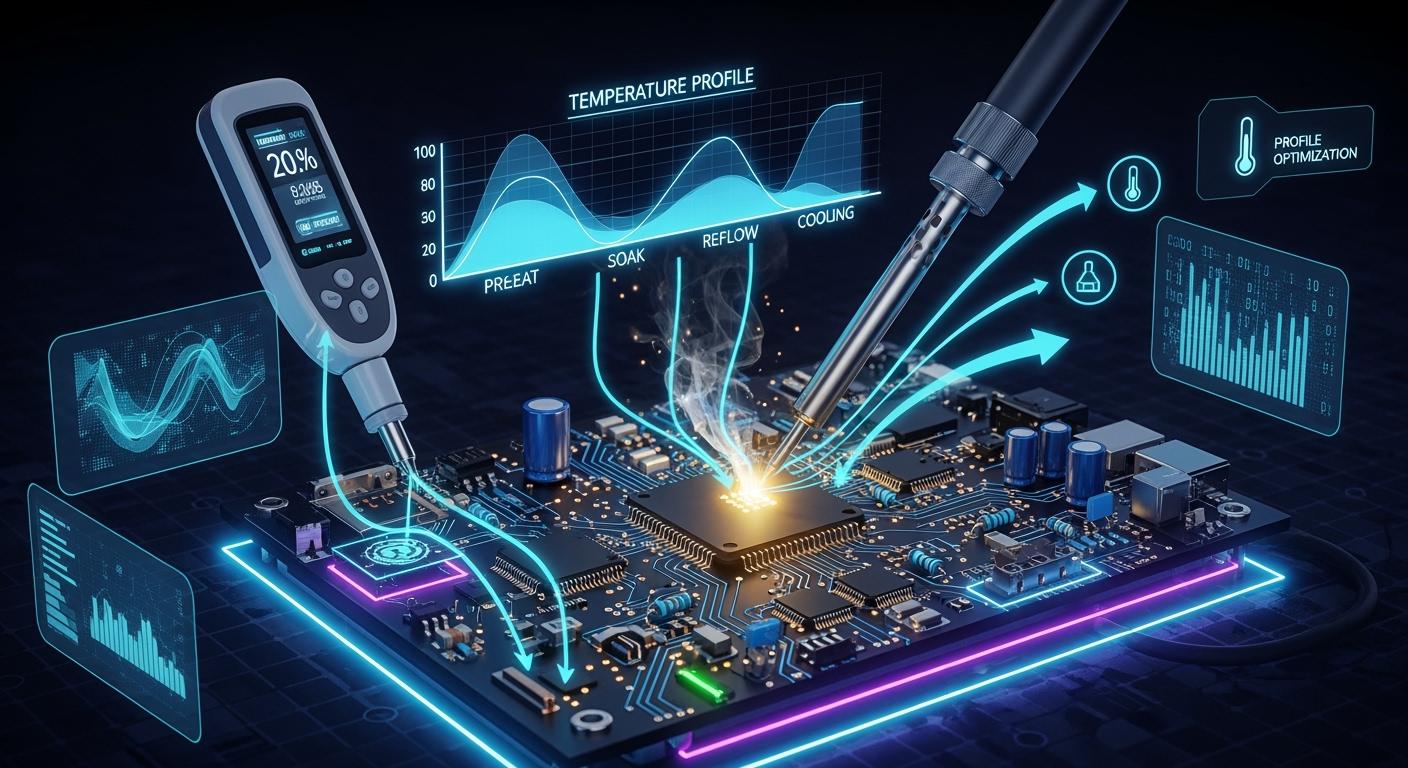
Key Phases of the Temperature Profile
There are four main steps in reflow soldering. Each step helps make sure the pcb connections are good.
Phase | Temperature Range | Duration |
|---|---|---|
Preheat | 25°C to 150°C (leaded), up to 180°C (lead-free) | 60 to 90 seconds |
Soak | 150°C to 200°C (leaded), 180°C to 220°C (lead-free) | 60 to 120 seconds |
Reflow | 210°C to 240°C (leaded), 240°C to 260°C (lead-free) | 30 to 90 seconds |
Cooling | From peak temperature down to below 50°C | 30 to 60 seconds |
First, you preheat to slowly warm up the board. This keeps it from breaking from fast heat. Next, the soak step spreads heat evenly. The reflow step melts the solder and makes the joint. Cooling makes the joint hard and stops big grains from forming. Cooling should be between 3–6 °C per second. This keeps the board safe and makes the grains right.
Why Profile Optimization Matters
You need to set the right temperature profile to stop problems and make the pcb last longer. A good reflow profile heats the solder paste just right. This helps stop cold joints, voids, and tombstoning. Good settings also keep the board from breaking when it cools. This way, you get strong solder joints and fewer problems later.
Tip: Always check the reflow profile. This helps you find mistakes early and keep your soldering good.
Temperature Profile Optimization Steps
Reference Standards and Guidelines
You should follow industry rules for the best results. IPC-7530 gives clear steps for temperature profiling in mass soldering. This rule helps you set the right reflow profile for both leaded and lead-free soldering. IPC-610 also tells you what makes a good solder joint. These rules help you stop soldering problems and make your pcb better.
You need to watch the peak temperature and time above liquidus (TAL). For lead-free reflow soldering, experts say the peak temperature should be between 235°C and 250°C. TAL should be between 30 and 60 seconds. The table below shows common values from different sources:
Source | Peak Temperature (°C) | Time Above Liquidus (TAL) (seconds) |
|---|---|---|
Fast Turn PCBs | 235–250 | 30–60 |
Wevolver | 235–250 | 30–60 |
LTPCBA | N/A | 30–60 |
Compuphase | N/A | 40–80 |
Note: Always check what your solder paste is made of. Lead-free alloys need higher heat than tin-lead pastes. Change your reflow profile if your solder paste melts at a different point.
Analyze PCB and Components
You need to look at your pcb and parts before you set the reflow profile. Every board is different. Board thickness, copper weight, and how many surface-mount technology devices you have change how heat moves. If you use a basic reflow profile, you might get weak solder joints or other problems.
Board thickness changes how heat spreads.
Copper weight changes how fast the pcb heats up.
SMT components need more heat and longer soak times.
Layer count and power planes also change the thermal profile.
You should check if your parts are sensitive to heat. Some parts can get damaged if they get too hot. Big parts may need more time above liquidus to solder right. Always read the datasheets for each part.
Set Initial Profile Parameters
You can start with normal settings for lead-free reflow soldering. The table below shows common values:
Parameter | Value Range |
|---|---|
Temperature Range for Lead-Free Alloys | 230-245°C |
Time Above Liquidus (TAL) | 60-150s |
Peak Temperature (TP) | 255-260°C |
Time within 5°C of Peak Temperature (TP-5°C) | 20-30s |
You can use special software to make a virtual reflow profile. This software helps you guess how your pcb will react to heat. Virtual profiling saves time and money. It uses old data and smart computer programs to pick the best settings. You do not need to put sensors on your board for every test. The table below shows why virtual profiling is helpful:
Advantage | Description |
|---|---|
Efficiency | Virtual profiling is faster than old ways. |
Non-intrusiveness | No need for real sensors during setup. |
Historical Data | Uses old data to guess thermal profiles. |
Real-time Monitoring | Watches the reflow process as it happens. |
Proactive Corrections | Finds problems early and makes quality better. |
Cost Reduction | Saves money by doing less physical testing. |
Tip: If you use nitrogen in your reflow oven, you can stop oxidation and make solder joints better. Nitrogen lowers surface tension and helps solder flow well. Keep oxygen under 1000 ppm for the best results.
Measure and Adjust Profile
You need to check the real temperature during reflow soldering. Put thermocouples on your pcb to record the time-temperature curve. Use tools like the Datapaq® Reflow Tracker system. This tool watches the whole reflow process and helps you find problems early.
Thermal profiling shows how heat moves through the pcb.
You can change oven settings and conveyor speed using the data.
Watching in real time helps you keep things steady and stop defects.
Reading the temperature profile data is important. Look at the reflow profile steps, peak temperatures, and time above liquidus. If you see something wrong, you can change your oven settings. This makes soldering better and more reliable.
Note: Use ovens with many heating and cooling zones. These ovens give you more control and help you get the same results every time.
Evaluate Solder Joint Quality
After reflow soldering, you need to check the solder joints. Look for signs of good soldering and problems. How the surface looks, physical problems, and part alignment show if the joints are strong.
Shiny finish means a good joint.
Dull, rough surface means a cold joint.
Cracks or gaps show the bond is not complete.
Ball shapes mean poor wetting or not enough heat.
Lifting leads can hide cold joints.
Bad solder joints may look patchy, have tiny bubbles, or a gray-sandy look. These signs mean the solder did not flow or bond well.
You can use X-ray and cross-section analysis for tricky boards. X-ray finds hidden problems under BGAs and QFNs. It shows voids, bridging, and not enough solder. Cross-section analysis lets you see layer thickness, voids, and cracks. These ways help you make sure your board is reliable and stop soldering problems.
Tip: Always check your pcb after reflow. Use your eyes and special tools to find hidden problems and make solder joints better.
Practical Tips for Reflow Optimization
Tips for Consistent Results
You can get steady results in reflow soldering by using some simple steps. Start with the settings your equipment or solder paste maker suggests. Watch the reflow process and check for signs of good soldering. If you see problems, change the temperature a little, like 5–10°C. Test after each change to see if you meet quality standards.
Calibrate your reflow oven often. This keeps the temperature profile steady and helps you avoid soldering defects.
Use a process control fixture to check that your oven works the same way every time.
Pay attention to how you load your pcb and the space between boards. These factors can change how heat moves during reflow.
Understand how fast your oven recovers heat when you add more boards. This helps you keep the reflow profile stable.
Tip: Clean your oven and check airflow often. Good airflow gives you even heating and better solder joint quality.
Common Pitfalls to Avoid
Many people make the same mistakes during reflow soldering. The table below shows common errors, their impact, and how you can fix them:
Mistake | Impact | Solution |
|---|---|---|
Variations of even 5°C can cause uneven soldering, leading to defects. | Regularly calibrate the oven and ensure proper functioning of fans and heaters. | |
Conveyor Speed Variations | Incorrect speed can prevent proper heating or cooling of the PCB. | Adjust speed based on board complexity and monitor dwell times in each zone. |
Poor Stencil Printer Alignment | Misalignment can lead to inconsistent paste deposits and defects. | Use vision systems for alignment and regularly inspect squeegee blades for uniform pressure. |
If you set the wrong conveyor speed or zone temperature, you can get cold solder joints or even burn parts. When the conveyor moves too fast, the pcb does not heat up enough. This causes poor wetting and weak solder joints.
Troubleshooting Profile Issues
If you see problems like poor wetting or solder bridging after reflow, you need to fix them quickly. Poor wetting often happens because there is too much oxidation in the solder paste. Try lowering the heat during preheating and keep the reflow time short. Use fresh solder paste and check your stencil design. Adjust your reflow profile so the pcb heats evenly.
Keep your oven clean and check the airflow to avoid uneven heating.
Watch the temperature in real time and adjust the reflow profile as needed.
Use thermal profiling data to find cold solder joints. Look for low peak temperatures or not enough time above liquidus.
Follow surface-mount technology rules for pcb and pad design to prevent soldering defects.
Note: Good reflow soldering and a well-optimized reflow profile improve reliability and reduce defects in your assemblies.
You can make the reflow soldering process better by using good steps. Begin by reading the solder paste instructions. Use thermocouples to check the temperature. Try soldering a few boards first. Change your profile for each board if needed. Keep watching and make small changes as you go. This helps you have fewer defects and stronger boards. Many factories have up to 70% less soldering problems with these steps. For more information, look at IPC-7530 and advanced reflow soldering methods.
FAQ
What is the most important part of a reflow temperature profile?
You need to control the time above liquidus (TAL). This step melts the solder and forms strong joints. If you set TAL wrong, you may get weak or cracked solder connections.
How often should you check your reflow oven profile?
You should check your oven profile every time you change boards, solder paste, or components. Regular checks help you catch problems early and keep your process stable.
Can you use the same profile for all PCBs?
No, you cannot. Each PCB has different materials and parts. You must adjust the profile for each design to get the best solder joints.
What tools help you measure the reflow profile?
You can use thermocouples and thermal profilers. These tools track temperature at different spots on your board. They help you see if your oven heats each area correctly.
See Also
Essential Temperature Curve Guidelines for Effective SMT Reflow
The Influence of Temperature Zones on PCB Solder Quality
The Importance of Temperature Profiling for Soldering Excellence
Key Process Criteria for Successful SMT Reflow Soldering
Frequent Problems Arising from Inadequate Temperature Distribution