Robotic Arm Controller PCBA Design
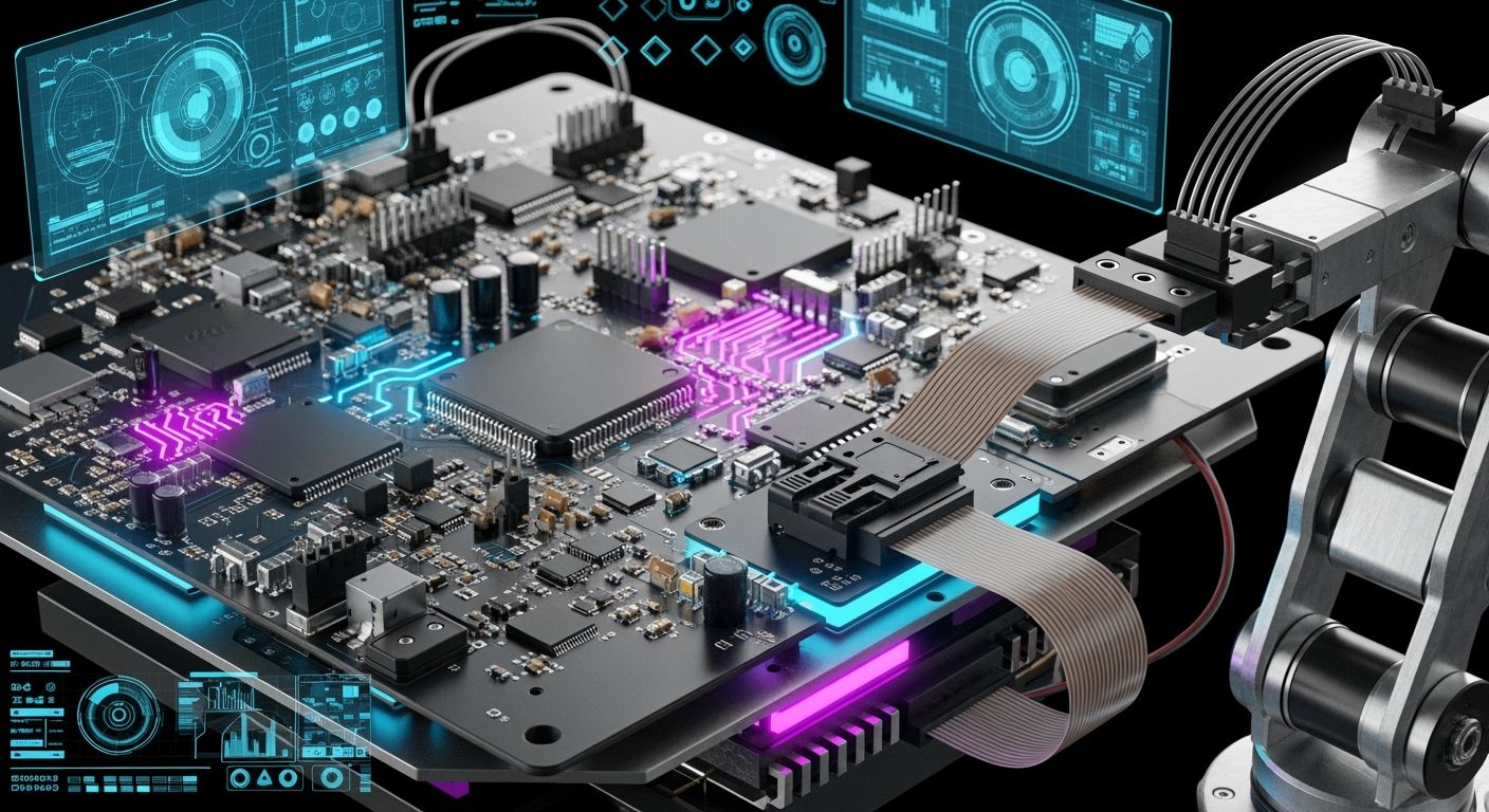
Modern industrial automation relies on advanced robotics. You must build every strong electronic controller around a tough pcba design. A successful robot arm controller needs high power density, fast feedback processing, and synced multi-axis control. You must also ensure strong noise immunity across the whole system.
Designing a compact robot pcb creates real engineering challenges. High motor switching currents can easily disturb sensitive encoder signals. Constant mechanical motion also threatens long-term electrical reliability. Therefore, your robot pcb design needs heavy copper traces, effective isolation topologies, and precise gate drivers. You can get total durability by building your controller to strict IPC Class 3 standards, ensuring every microcontroller operates smoothly.
Key Takeaways
Packed robot circuit boards need powerful microcontrollers and quick motor drivers to control movements along several axes.
GaN power modules increase switching speed and energy efficiency compared to standard silicon MOSFETs.
Thick copper lines and heat-draining hole patterns lower inside temperatures when motors run hard.
Reinforced isolation topology keeps high-voltage motor circuits away from delicate low-voltage microcontrollers.
Putting decoupling capacitors in the right spots stops voltage jumps near the motor driver pins.
Following IPC Class 3 standards guarantees the best electrical performance when the board faces constant physical stress.
Thorough motor testing and heat imaging check the board's work before its final use.
Core Architecture for Robot Arm PCBA Design
Building a working hardware layout needs smart choices for main chips and power supply networks. A modern pcba design balances high-speed computing with strong motor drivers. Designing a tough robot arm takes precise time management for every joint.
MCUs and Multi-Axis Motion Control
Your system uses a main digital controller board to calculate complex movements. Real-time pathing math creates accurate signals to drive the motors.
STM32 and FPGA Processors
Factory settings need more processing speed than standard circuit boards can offer. Designers often pick 32-bit STM32 microcontrollers or FPGA chips to manage instant tasks. A modern microcontroller handles fast feedback loops by reading position data quickly. Processors like Texas Instruments C2000 DSP (F28P65 family) control six motors together to run multi-axis movement. FPGAs execute several complex paths at the exact same time. Advanced controller hardware coordinates matching motion across joints while keeping networks stable. Your robot pcb uses fast processing chips to keep delays low during quick movements.
Scaling from Arduino Controlled Robot Arm Architectures
Engineers often start building systems with easy-to-use development boards. An arduino controlled robot arm provides a great starting point for early testing.
Architecture / Component | System Capability | Target Motion Architecture |
|---|---|---|
ATmega2560 (16 MHz) | Controls 4 to 6 axes with simple feedback | Basic platform test setups |
32-bit ARM Cortex-M | Runs fast PID loops at 100 to 1000 Hz | High-speed multi-axis motion |
Basic setups run simple position control loops that compare target positions with measured positions. Upgrading from a simple arduino controlled robot arm to factory hardware requires a better main microcontroller. You must switch to higher processing power to keep real-time control without skipping steps. The upgraded robot pcb handles larger current loads without getting too hot.
Power Stages and Gate Drivers
The power stage turns digital command signals into actual physical motor force. Choosing a high-density robot pcb saves board space while managing heat efficiently. A dedicated microcontroller watches for system faults.
MOSFET vs GaN Power Modules
Designing a reliable robot pcb requires strong power parts. Regular silicon MOSFETs offer steady current control for normal board designs. Newer Gallium Nitride (GaN) power modules allow faster switching speeds and higher power density. Higher switching speeds reduce the size of filters on your controller board. You get cooler board running temperatures while keeping high electrical efficiency and great robot drive efficiency.
Multi-Joint Servo and Stepper Drivers
A high-density robot pcb powers several joint motors at the same time. You can use built-in driver ICs for small joint motors or discrete switching circuits for heavier loads. Modern drive systems control up to 8 servo motors or 6-axis stepper setups. Compact driver sections stop magnetic noise between nearby power channels on the physical board. This layout guarantees smooth robot joint movement during all operational tasks.
Sensor Feedback and Wireless Interfaces
Feedback systems give exact position data for every joint axis. Each robot pcb needs separated trace paths to guard fragile data lines.
Quadrature and Absolute Encoders
Getting high position accuracy requires picking the right encoder for your robot pcb design. Every robot arm joint needs exact position updates to stay steady.
Requirement | Quadrature (Incremental ABZ) | Absolute Encoders |
|---|---|---|
Signal Output | Two 90-degree offset square waves A/B plus Z index pulse | Unique digital multi-turn word via BiSS-C or SSI |
Resolution | 1024 to 8192 PPR | Up to 20-bit in integrated magnetic drives |
Power-Cycle Behavior | Position is lost; homing routine required | Position retained across power cycles |
A good pcb design routes encoder lines away from motor power traces to protect signal quality. Every robot pcb needs low-noise wiring for clean signal pulses. Blocking noise ensures accurate robot joint placement. Clear signals allow reliable robot arm operation.
Integrated Bluetooth and Fieldbus Modules
Modern industrial factories need wireless control and fast network connections. Adding short-range wireless chips allows easy phone app control during early testing. Industrial Ethernet networks give reliable data sharing across factory systems.
Protocol / Wireless Option | Cycle Time / Latency Characteristic | Application Role |
|---|---|---|
PROFINET IRT | Cycle time below 50 µs, jitter below 1 µs | Hard real-time deterministic synchronization |
EtherCAT | Low-latency telegram processing with jitter usually < 1 µs | Fast motion data transit between nodes |
Bluetooth 5.4 | Wireless communication protocol | Cable-free parameter tuning during prototyping |
Smart communication chips improve robot arm control on automated assembly lines. A well-designed robot pcb boosts machine connections while keeping signal lag very low. Smart pcb design choices ensure steady joint movement under heavy working loads. Good pcb layout protects sensitive data lines while powering large robot motors. This strong setup supports heavy robot arm work under real factory conditions. High power density increases the total lifting capacity of the robot arm. You can check robot movement data and enforce safety limits using built-in hardware checks. This solid electronic controller design improves robot performance in harsh working environments. Advanced manufacturing methods get your robot hardware ready for full production.
Thermal Management for Heavy-Load Robot PCB
Heavy motor loads generate extreme heat across your robot pcb layout. You must manage thermal pathways effectively to ensure reliable motion control stability under full joint torque.
Board Stackup and Heavy Copper
Your power delivery network needs continuous cooling pathways inside the board structure. Designing a dedicated board layer arrangement protects weak signals while routing high currents.
Layer Assignment for Power Planes
A multi-layer printed circuit board distributes motor supply voltages efficiently. You should place internal power planes adjacent to solid ground layers to create built-in capacitance. This arrangement lowers impedance while spreading localized heat across the surface area. Placing high-current motor supply traces on outer layers improves convective cooling for every heavy-load robot arm axis.
IPC-2152 updates the old IPC-2221 conductor-sizing charts by measuring data from different board designs. For power planes, you should select heavy copper width using IPC-2152 charts because the standard accounts for copper weight and plane proximity heat spreading.
Heavy Copper Traces for High Current
Heavy motor currents demand thick copper traces across your robot pcb. The standard IPC-2221 calculation uses the conductor cross-sectional area equation I = k × ΔT^0.44 × A^0.725. The constant k equals 0.048 for external layers, while internal layers use k equal to 0.024.
IPC-2152 charts summarize the relationship between thermal conductivity, PCB thickness, trace width, and plane area.
The IPC-2152 calculator applies a plane correction factor, recalculating required copper area from the baseline.
This workflow directly supports heavy copper power plane selection for any high-power controller board.
Using heavy copper reduces trace resistance dramatically. Lower electrical resistance decreases internal heating inside every motor drive circuit. Proper pcb design ensures consistent power delivery to each joint actuator across your robot pcb layout.
Dissipation and Heat Sinks
Power components transfer heat into surrounding board regions during fast acceleration cycles. You must build active and passive cooling channels directly beneath hot driver parts on your robot pcb board.
Thermal Via Array Design
Placing thermal vias under driver components conducts heat away from silicon junctions. You can select specific geometric layouts to maximize total thermal transfer across your robot pcb assembly.
Parameter | Effective value |
|---|---|
Thermal via diameter | 0.3–0.5 mm |
Thermal via pitch | 1.0–1.2 mm |
Thermal via fill | Conductive epoxy; reduces junction temperature by 10–15°C |
A dense via grid transfers heat from the surface layer to internal plane layers. Conductive fills remove internal air pockets to speed up thermal conduction across your robot pcb design. Executing clean pcb design rules maintains low junction stress.
Integrated Heat Sinking and TIMs
Large motor driver modules require external heat sinks to clear thermal energy quickly. You place a thermal interface material (TIM) between the module surface and the heat sink.
Silicone grease provides thermal conductivity ranging from 1–5 W/m·K for standard applications.
Conductive gaskets offer thermal conductivity levels between 3–8 W/m·K under compression.
Liquid metal provides conductivity between 20–80 W/m·K for maximum heat removal.
Selecting a heat sink with thermal resistance under 5°C/W protects parts dissipating over 1–2 W. Advanced pcb design keeps driver temperatures well within safe operational bounds. Your robot pcb maintains optimal motion control during heavy robot arm lifting tasks. This robust thermal setup prevents system failure under full load. Every driver stays cool, protecting your complete hardware during continuous factory operations. Smart heat management extends total robot pcb lifespan across every demanding robot arm joint motion.
Signal Integrity and PCB Design Best Practices
Dynamic mechanical forces continuously stress electrical pathways in modern factory automation. Fast motor switching injects heavy electrical noise directly into nearby circuits. You must apply strict signal integrity techniques across your layout to keep motor movements smooth and precise. Protecting fragile control signals requires dedicated electrical boundary layers and clean power delivery networks.
Grounding and Noise Isolation
High-voltage motor circuits generate strong electric fields that easily corrupt sensitive control signals. Isolating logic zones from switching components protects your microcontroller from destructive ground loops and electrical spikes.
Galvanic Isolation Topologies
Separating power drives from logic networks requires robust physical and electrical boundaries. Designers select specific isolation ratings based on safety requirements and motor supply voltage levels.
Isolation class | Maximum isolation rating | Relevance to motor/logic isolation in robotic arm PCBA |
|---|---|---|
Functional & basic isolation | Up to 3 kVRMS | Provides one level of electrical isolation and basic shock protection, but lower robustness for high-voltage motor supplies. |
Reinforced isolation | Up to 5.7 kVRMS | Supports higher working voltages, wider creepage and clearance, making it the stronger choice for separating high-voltage motor supply from low-voltage logic regions. |
Using reinforced isolation creates a safe barrier between high-current drive components and fragile digital parts. You should place isolated gate drivers between the low-voltage processor and high-power switches.
Star Grounding and Split Planes
Continuous return paths keep high-frequency currents from radiating noise across your board. Avoid splitting your ground plane into isolated pieces because broken copper paths disrupt return currents and increase electromagnetic interference.
A complete, continuous ground plane provides the lowest-impedance return path for digital signals.
Functional zoning guides current return paths without breaking copper plane continuity.
Isolated DC/DC converters use a small cutout zone under the component with a single-point bridge.
Mixed-signal front-ends connect analog and digital zones through a single ferrite bead bridge.
Proper layout design keeps heavy motor currents away from delicate analog sensors. Routing signal traces over continuous reference planes prevents noise coupling between adjacent power zones.
Switching Noise and Decoupling
Rapid power switching creates voltage ripple across power rails. Placing storage capacitors near supply pins stabilizes system voltage levels during heavy acceleration cycles.
Decoupling Capacitor Placement
Motor driver ICs draw sharp pulses of current during each switching cycle. Installing small capacitors directly next to driver supply pins prevents local voltage drops.
Capacitor value / role | Placement guidance |
|---|---|
0.1 µF (100 nF) ceramic for high-frequency switching noise | Place as close as possible to the motor driver IC power and ground pins. |
1 µF to 10 µF for low-frequency ripple and bulk energy | Minimize trace length to the IC so trace inductance does not reduce filtering effectiveness. |
Smaller-value capacitor | Place closest to the device; connect larger-value capacitors after the smaller one. |
Increasing bypass capacitance from a small 1000 pF value up to 1 µF suppresses supply ripple effectively. Proper capacitor placement ensures clean rectangular power signals reach each active microcontroller component.
Snubber Networks for Phase Nodes
High-speed motor switching produces dangerous voltage spikes across inverter output phases. Resistor-capacitor snubber networks absorb fast voltage transitions at each phase node. Dampening high-frequency ringing lowers voltage stress across driver switches. Proper pcb design minimizes loop area around phase nodes to contain high-frequency radiation.
EMI Mitigation and ESD Protection
External cables act as antennas that collect outside electrical noise. Shielding sensitive inputs preserves fast control performance during intense factory operations.
Common Mode Chokes and Filters
Quadrature encoders track accurate motor positions during dynamic robot movement. Passing differential signal lines through low-pass filters blocks high-frequency common-mode noise.
Quadrature inputs sample position data while internal digital filters reject high-frequency system noise.
FPGAs sample input lines and update outputs only after three consecutive identical logic states.
Filtering adds minor propagation delay that position counting algorithms must take into account.
Filtered phase edges feed dedicated counters while index pulses reset position references.
Signal integrity metric / guideline | Acceptable value / practice | Relevance to quadrature encoder input on controller PCBA |
|---|---|---|
Edge rise/fall time | <100 ns on differential A/A/ (and B/B/) signals | Clean edges prevent miscounts due to slow transitions or noise |
Differential amplitude | >2.0 V (RS-422 minimum) | Receiver must see sufficient differential swing for reliable logic detection |
Common-mode voltage | 0–5 V range | Input common-mode tolerance helps avoid damage and false triggering |
Ringing/oscillation | None permitted on the line | Ringing can create extra edges, corrupting position count |
Z index behavior | One pulse per revolution, aligned with a known A/B state | Provides a repeatable reference for homing and position calibration |
Cable and termination | Shielded twisted pair; 120 Ω termination at receiver; single-point shield grounding | These constraints guide the controller PCBA's differential receiver and termination layout |
TVS Diodes for External Interfaces
External robot connectors expose internal components to static discharges. You must place transient voltage suppression diodes directly next to input headers.
Placing TVS diodes near external connectors clamps static discharges to safe voltage levels before high-voltage transients reach internal processing circuits.
Using short, wide traces to ground TVS diodes reduces parasitic inductance. This protective layout strategy ensures your robot controller withstands harsh factory static events without losing data. Careful execution of these rules guarantees total signal integrity for every robot arm joint.
DFM and DFA for High-Density Assembly
Component Spacing and Layout Rules
High-Current Track Clearances
You must keep enough space between high-voltage motor tracks and low-power signals on your robot pcb. Separate power and signal zones stop heavy motor noise from leaking into sensitive microcontrollers. You should use 1-4 oz copper for motor driver modules to carry high joint currents. Smart pcb design stops unexpected voltage drops.
Check your contract manufacturer DFM rules before setting your final board layer setup. You should pick a balanced, low-warp stackup with under 0.75% bow to prevent part alignment errors. Proper line spacing and wide copper planes protect your printed circuit board from heat damage and power noise. Smart pcb design ensures steady power delivery across the entire board.
Mixed SMD and THT Orientation
You should place surface-mount devices on the top layer to make building the board simpler. Compact layouts use surface-mount parts for microcontrollers and driver chips. You save through-hole parts for heavy pieces, frequently used connectors, and vibration-prone links.
Turning through-hole parts away from sensitive surface-mount devices protects delicate parts during soldering. Automated pick-and-place tools position fine-pitch packages across your robot pcb design with great accuracy. Strong mechanical mounts stop joint cracks on moving parts during fast robot arm actions. Clear pcb design rules make automated robot arm assembly run smoothly.
Manufacturing and Soldering Quality
IPC Class 3 Standards
Factory motion tools need high building quality to survive constant shaking and heavy physical stress. You must build your high-density controller board using IPC Class 3 rules for maximum working reliability. Good pcb design delivers steady electrical work under tough working conditions.
IPC Class 3 criteria require strict inspection standards, including micro-section analysis, automated optical inspection, and ionic contamination levels below 0.78 μg NaCl/cm².
Inspection Area | IPC Class 3 Criterion |
|---|---|
Through-Hole Solder Joints | Minimum 75% circumferential fillet required |
Component Placement Tolerance | Held within ±0.1 mm for standard parts |
Surface-Mount BGA Voids | Maximum allowable void content limited to 9% |
Following these rules ensures your pcba design works continuously without sudden power failures. Complete testing checks physical solder joints before final factory use. Strong circuit protection guards signal paths during high-speed robot arm actions.
Thermal Profiling for Reflow Soldering
Thick copper traces and mixed-size parts absorb heat unevenly during reflow soldering. You must adjust stencil design and heating settings to avoid solder bridges and cold joints on your robot pcb. Divided stencil cuts on large heat pads control solder paste volume very well. Better pcb design methods reduce building defects during assembly on your robot pcb.
Using vacuum or vapor-phase reflow keeps ball grid array empty spaces below 10%. Targeted soldering handles through-hole motor links without hurting nearby surface-mount parts. Exact heat testing guarantees strong solder joints, giving your robot arm great strength during non-stop motion tasks. Efficient assembly techniques boost total production output for every robot pcb board.
Testing and Quality Assurance for Robot Arm Controllers
Circuit and Functional Testing
Test Point Matrix Design
Rigorous testing validates your board before final installation. You must place dedicated test points across every critical net on your robot pcb. Automated bed-of-nails fixtures touch these test points to measure trace continuity and operating voltages. Proper pcb design ensures unhindered access for test probes during factory production.
Your test point grid isolates digital lines from power drivers. You verify each signal track before applying full operating power. Automated voltage testing checks power rails for unexpected short circuits. Reliable testing prevents damage to sensitive components on your controller board.
Dynamic Motor Load Simulation
Simulating motor movements exposes electrical weakness under dynamic load conditions. You connect electronic loads to simulate real robot joint torque on your robot pcb driver stages. This functional testing verifies drive currents without risking physical hardware damage. Active feedback loops maintain steady position control during sudden power shifts.
Your microcontroller manages drive routines while testing equipment captures phase currents. Test systems monitor signal stability during sharp motor acceleration cycles. You check logic responses under maximum current draw to protect your main controller. Dynamic testing ensures smooth robot arm motion across all operating axes.
Environmental Stress Testing
Thermal Imaging Under Full Load
High-power robot movements generate internal heat during heavy operations. Infrared cameras scan your working robot pcb under maximum current stress. You identify hot spots on power drivers during extended thermal testing. Smart pcb design paths spread thermal energy away from fragile processing units.
Thermal testing under full load verifies heat dissipation across copper layers and prevents premature hardware failures.
You measure temperature drops across thermal via arrays under continuous duty cycles. Infrared testing confirms proper thermal pad contact under high-current components. Safe temperatures ensure long-term robot reliability during intense factory workloads.
Vibration and Shock Validation
Industrial robot environments subject every internal robot mechanism to constant mechanical shaking. You mount your assembled hardware onto multi-axis vibration tables for physical stress testing. Vibration testing exposes weak solder joints and loose connector latches on your robot pcb. Heavy robot arm movements test mechanical durability under severe operational shock.
Secure the unit onto the vibration table using rigid mounting hardware.
Execute low-frequency vibration sweeps to identify system resonance frequencies.
Apply high-g shock pulses along three orthogonal axes to test structural joint strength for heavy robot tasks.
Post-shock testing confirms consistent board operation after severe physical impacts across the complete robot system. Rigorous environmental testing guarantees robust performance for every robot arm controller.
Building a reliable robot arm controller takes careful planning. You get great motor control by combining smart part choices, active heat management, and strong noise blocking. Safe PCB rules and testing make sure your hardware survives real factory work. Following IPC Class 3 rules protects your microcontrollers from physical stress.
Modern robotics brings exciting electronic trends to factory settings. New fast materials like GaN and SiC increase power in small PCB spaces. Advanced chip designs and built-in AI make systems last longer. Smart layout choices increase lifting power and movement accuracy. You build better robot arms for hard tasks by using strong PCB design habits.
FAQ
Why do you need IPC Class 3 standards for a robot arm board?
IPC Class 3 standards protect your board from harsh factory shaking and continuous mechanical stress. Class 3 limits BGA component voids to 9% and requires 75% solder fillet fill for through-holes. These strict building rules stop unexpected power failures during motion.
How do you isolate motor switching noise on a robot pcb?
You block high-voltage motor noise by placing reinforced isolation parts between low-voltage logic circuits and gate drivers. Dividing component zones over a solid reference plane keeps motor ground loops away from sensitive digital signals on your board.
What testing steps ensure board reliability under heavy loads?
Automated bed-of-nails tools check circuit connections before you apply full power. You then start dynamic motor testing with simulated electronic loads. Finally, thermal imaging scans locate hot spots on driver stages under heavy current stress.
Why should you use heavy copper on your robot pcb?
Thick copper traces lower heat creation during rapid motor acceleration cycles. You choose trace sizes based on IPC-2152 standards. Lower electrical resistance maintains steady current delivery to every joint motor without overheating internal board layers.
How does vibration affect controller dynamic performance?
Mechanical shaking puts constant physical stress on solder joints and real connectors. You run multi-axis vibration testing on a robot arm to locate resonance points. Post-shock checks confirm that electrical paths stay fully working after hard impacts.
How do TVS diodes protect an industrial robot?
External cables gather dangerous static electricity during normal factory work. You install TVS diodes near outside connectors to send high-voltage electrostatic discharge spikes safely into the ground. This setup keeps static away from delicate processing chips inside your machine.
See Also
Essential Design Tips For Building Reliable Industrial Controller PCBs
The Ultimate Beginner Guide To Sourcing PCBA Bill Materials
Understanding Printed Circuit Board Assembly And Its Key Components
Best Practices For Procuring Electronic Components In PCBA Manufacturing
