How to Assemble and Solder Security Camera PCBA Efficiently
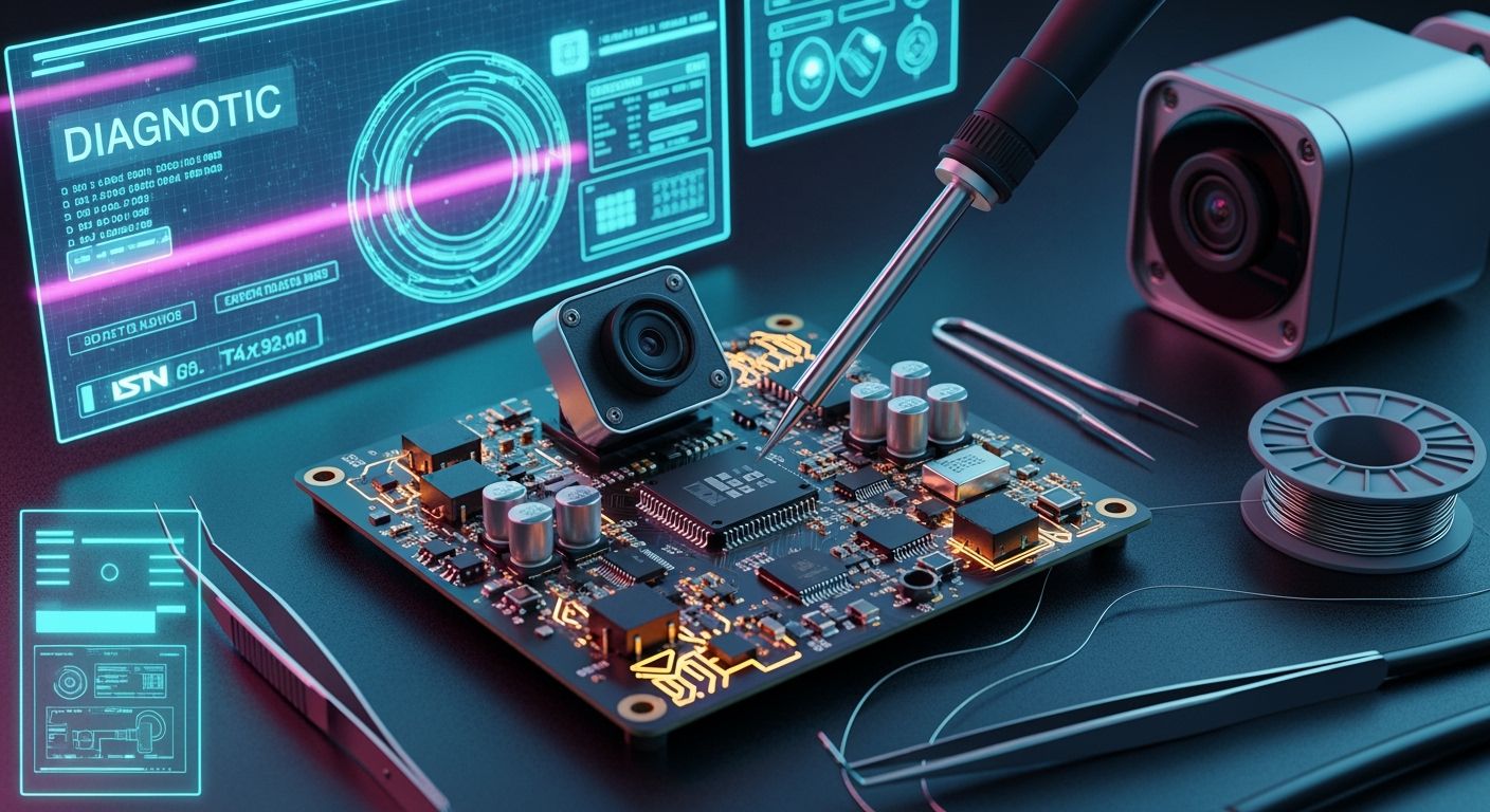
You must improve your IP camera PCB production line for better results. Standard PCBA manufacturing needs careful environmental controls to work well. You should use an ISO 7 or Class 10,000 cleanroom while soldering. You need SAC305 Type 4 or Type 5 solder paste. Type 4 paste has small particle sizes of 20-38 micrometers for 0.5 mm pitch stencils. Type 5 paste uses 10-25 micrometers for a pitch below 0.4 mm. You must balance speed with signal integrity and heat dissipation during security camera PCB soldering. Careful CMOS image sensor placement keeps surveillance quality high. Follow this DIY electronics assembly guide to learn CCTV PCB assembly and manufacturing of your IP camera PCB hardware using automated inspection.
Key Takeaways
Manage static electricity and use clean rooms to keep delicate camera pieces safe from harm and dirt.
Put exact solder paste on using smooth metal stencils to make neat connections on very small chips.
Follow strict heat settings during reflow soldering to safely attach the main video processor chips.
Put optical image sensors in super clean areas to keep the camera focus sharp and pictures clear.
Check each circuit board with 3D camera and X-ray tools to find hidden soldering mistakes.
Tooling and PCBA Manufacturing Preparation
Equipment Setup and ESD Control
You must carefully prepare your workspace and assembly line before beginning IP camera PCB production. Follow the ANSI/ESD S20.20 rules to create a strong static electricity control program in your factory. Workers wear grounded wrist straps and walk on special conductive floor tiles to protect each IP camera PCB from sudden static shocks. Air ionizers work constantly to remove static charges from objects near the assembly line that cannot be grounded. You can read this DIY electronics assembly guide to learn how to set up your SMT equipment correctly.
Automatic SMT machines make camera PCB manufacturing faster while keeping strict control over every step. A solder paste printer puts paste onto metal pads accurately, and a pick-and-place machine places surface-mount parts very fast. Solder paste inspection tools measure the exact height of the paste printed on every IP camera PCB. Automated optical inspection devices then check the quality of solder joints on each CCTV camera PCB. Setting up your equipment this way guarantees high-quality PCBA manufacturing for modern high-definition video devices.
DFM and Stencil Design Standards
Good design for manufacturing rules protect video signal quality and help heat escape from your IP camera PCB. Keep enough space around high-frequency MIPI lines, and add proper EMC shielding layouts across the board layers. You can use these security camera PCB building tips to improve complex multi-layer board designs. Checking signal impedance values helps you prevent unwanted video noise on every IP camera PCB you make. Follow this CCTV PCB assembly tutorial to check your design files quickly and easily.
Stencil design controls how accurately paste prints onto small video processors and power management ICs. Choose laser-cut, electro-polished stencils that are 0.08 mm to 0.10 mm thick to get clean openings. An aperture area ratio above 0.66 lets the solder paste slide out smoothly during printing. These security camera PCB building tips prevent solder bridges from shorting small, closely spaced parts. You can follow this CCTV PCB assembly tutorial whenever you build your next IP camera PCB. These helpful steps speed up production and keep your PCBA manufacturing quality consistent on every run.
Security Camera PCB Soldering and Reflow
Solder Paste Deposition and SPI
Clear off all surface dirt before you begin security camera pcb soldering. Cleaning the ip camera pcb well helps the paste stick and creates much stronger solder joints. Workers adjust automatic printing machines so they can spread the SAC305 paste with high accuracy. Good stencil designs let you control the exact amount of solder on small pads. Solder paste inspection devices gather measurements right away to check every paste volume parameter.
Clean each ip camera pcb board surface to prevent solder joint defects during production.
Apply SAC305 paste using smooth electro-polished stencils to achieve very accurate soldering results.
Check the solder volume data right away to catch any printing mistakes early.
Accurate paste printing gives you a great base for soldering parts during surface mount assembly. Workers check ip camera pcb test results often to catch small changes in solder paste amounts. Read this guide to learn security camera pcb building tips about maintaining your metal stencil. Using these steps helps you succeed when soldering components onto a camera pcb in mass production.
SMT Reflow Profiling for SoCs
Main processor chips need carefully controlled heating cycles during the reflow process. Warm up your ip camera pcb slowly at 1°C to 3°C every single second. Nitrogen ovens keep oxygen levels below 500 ppm while holding heat at 150°C to 180°C for 60 to 120 seconds. Top reflow heat hits 235°C to 245°C to give you perfect security camera pcb soldering results on each ip camera pcb.
Keep oxygen below 100 ppm inside the reflow oven to stop rust on sensitive video processor chips.
Dry out sensitive chips at 125°C following J-STD-033 rules before you start soldering them. Good thermal pad layouts lower empty air pockets under main chips, boost overall soldering work, and protect important video features. Cooling the board down at 1°C to 4°C per second hardens liquid solder safely. Read these security camera pcb building tips to improve heat flow across your whole ip camera pcb. Using these steps for soldering components onto a camera pcb helps you build a solid ip camera pcb and keep factory yields high.
High-Precision CCTV Camera PCB Sensor Assembly
Cleanroom CMOS Sensor Mounting
Handle sensitive CMOS sensors in ISO Class 5 to 7 cleanrooms to keep tiny dust off lenses. Special HEPA filters clean the air by trapping tiny dust pieces as small as 0.3 microns. Keep room temperatures near 22°C and set humidity levels between 40% and 60% for best results. Workers wear full cleanroom suits and run air ionizers to destroy static charges on every ip camera pcb. Careful board handling stops dirt from ruining camera image quality when you build an ip camera pcb.
Exact heat control stops the board from bending during low-temperature soldering steps. Add thermal vias and thick copper areas under parts to protect the base material. Good grounding cuts image noise caused by power ripples over 20mV. Grounded shields also block unwanted electrical noise from reaching delicate analog signal lines. Using careful automated soldering methods keeps video signals sharp across your ip camera pcb during big production runs.
Optical Alignment and Lens Fitting
Use active optical alignment tools during lens module installation to get very sharp camera focus. A multi-axis robotic station shifts optical parts while constantly measuring target focus data. The computer checks image contrast and modulation transfer function numbers to reach extreme micrometer accuracy. This smart setup increases first-pass build success from 85% to over 98% on high-resolution cameras. Correct alignment places lenses right over the sensor center on your ip camera pcb. Follow these steps to place parts without breaking small circuit traces.
Fast video signals travel across an ip camera pcb on matched pairs that need careful trace routing. Keep digital interface trace lengths equal so you never lose video frames during recording. Put fast-drying UV glue around the module base after completing active alignment. This gluing step locks lens parts onto the cctv camera pcb without causing damaging physical stress. Automatic tools check soldering temperatures constantly while attached cctv components bond to the board.
Careful part handling protects delicate circuit pieces from heavy physical stress during high-precision board assembly. Technicians test fast image data lines before fully curing the optical lens mount. Low-temperature soldering holds side leads firmly while keeping the board completely flat. Standardizing all assembly steps on your ip camera pcb line ensures reliable camera performance. Keeping regular data logs lets you track optical calibration settings across every ip camera pcb batch.
CCTV PCB Assembly for Power and Network Interfaces
PoE and BNC Interface Soldering
Installing reliable power and network connectors is a critical step when making an ip camera pcb. The IEEE 802.3bt Power over Ethernet standards send up to 90W of energy to the system. Managing this high power requires smart circuit routing and good cooling choices while soldering parts. Matching Gigabit Ethernet traces at 100 ohms protects video data from getting lost along the path.
Interface Component | Assembly Specification | Primary Function |
|---|---|---|
Ethernet Controller | QFN Package | Manages network signal integrity and routing |
PoE Processor | BGA Package | Handles power delivery up to 90W safely |
You must keep power levels steady in PoE setups to clear away electrical noise and voltage jumps near camera parts.
Place power parts in a straight line starting from the RJ45 jack down to the DC-DC converter. Following this exact layout order keeps the camera system running continuously without resetting itself. Use 3D X-ray tools to check hidden solder connections under large chips. Learning these steps will improve your daily work during security camera pcb soldering projects.
Selective Wave and Hand Soldering
Careful heat settings are necessary while soldering components onto a camera pcb. A selective soldering machine directs liquid metal right onto tall wire pins without burning small surface parts nearby. This controlled method works much better than basic wave machines for tricky circuit boards.
Spray liquid flux only on the specific wire pins that need power.
Warm up the board section slowly to stop sudden heat damage.
Move the melted solder tip along a pre-set path to finish joints.
This helpful guide protects fragile camera lenses when soldering components onto a camera pcb with mixed parts. Send simple boards through a 260°C wave machine after warming them to 100°C or 150°C. Workers need enough flux during board repairs to help molten solder stick correctly to metal pads. Touch hot iron tips to the board briefly so delicate copper pads never peel off. Try these practical tips to increase your total output during your next ip camera pcb run.
Quality Inspection for Surveillance Hardware
Automated Optical and X-Ray Inspection
You must inspect every ip camera pcb thoroughly to keep product quality high on the line. Fast 3D Automated Optical Inspection tools scan surface parts quickly. These cameras spot missing pieces, bad solder bridges, and wrong polarity right away. Smart software compares live pictures with design files to check part placement on the board. You can follow this guide to set up your SMT optical inspection tools easily.
Hidden solder joints under large chips need non-destructive 3D X-ray inspection tools. X-rays pass through thick boards to check BGA connections, ground vias, and power ICs. The software finds hidden solder voids and short circuits that visual cameras miss. You save this inspection data to track quality trends across all production runs over time.
Signal Integrity and Power Testing
You check electrical stability before sending each ip camera pcb to final testing steps. Engineers test power distribution lines to confirm correct voltage levels across all board sections. Sending quick electrical pulses triggers the mechanical IR-cut filter to test light switching functions. Oscilloscopes measure main system clock signals near 27 MHz to stop video errors.
Live video checking guarantees smooth image delivery over your ip camera pcb network. You attach an oscilloscope to test digital video streams or analog 1V peak-to-peak signals. Time Domain Reflectometry tests fast trace impedance to clear away video noise. Checking your ip camera pcb with these electrical tests ensures steady data transfer and hardware reliability. This strict testing process protects your ip camera pcb from unexpected failure in cctv setups. You protect every ip camera pcb and security camera build by keeping high quality.
Yield Optimization and Defect Prevention
Smart factory monitoring stops common building mistakes on your security camera pcb. Engineers study daily test records to catch tiny production changes early. Smart teams also study potential board failures to spot weak spots fast. Helpful problem-solving methods like asking the 5 Whys fix board flaws quickly. Following these quality checking tips keeps factory success rates very high every day.
Conformal Coating Application
Outdoor camera boards need clear protective coatings to resist bad weather. You apply thin shield layers to safeguard delicate camera manufacturing parts against rain and dirt.
Application Method | Coating Material | Key Benefit |
|---|---|---|
Automated Spraying | Acrylic | Uniform thickness and fast drying |
Manual Brushing | Urethane | Simple use and chemical resistance |
Dipping | Silicone | Complete coverage and heat resistance |
Adding power surge parts guards outdoor camera hardware against strong electrical jumps. Plan detailed board checkups every 6 to 12 months to spot swollen power parts early. Protecting each ip camera pcb this way ensures strong hardware performance for years.
Rework Methods for Fine-Pitch ICs
Fixing broken chip leads takes soft heat and careful hand tools. You can clear connected solder pins on a fine-pitch ip camera pcb by completing three easy actions.
Spread fresh liquid flux directly across the shorted metal pins.
Pull a warm soldering iron tip over the pins to clear away excess solder.
Wash the freshly repaired board surface using alcohol to wipe off dirty flux spots.
Workers follow exact repair steps when fixing any damaged ip camera pcb. First, lift the bad chip using a warm air heating tool. Next, check underlying metal pads for loose or torn copper lines. Then, align a fresh chip over the pads in the right direction. Finally, solder all metal pins carefully to hold the part tight. Using these helpful repair steps increases fixed board counts and keeps every ip camera pcb running smoothly.
You optimize high-yield pcba manufacturing by executing precise workflow stages. Accurate SMT reflow profiles protect video processors. ISO cleanrooms ensure complete optical sensor care. Durable power interfaces prevent network drops. Always keep solder voiding limits under 10% to maximize thermal performance. Micron-level sensor alignment tolerances and signal integrity tests secure ultimate image quality. This DIY electronics assembly guide helps you control every ip camera pcb production line and improve pcba manufacturing overall. Following strict cctv pcb assembly steps elevates your factory yield. Execute flawless security camera pcb soldering on every ip camera pcb. Adhering to IPC-A-610 Class 2/3 manufacturing standards guarantees long-term operational stability for all surveillance hardware using a high-grade ip camera pcb.
FAQ
What cleanroom standard do you need for CMOS sensor mounting?
You must place CMOS image sensors inside an ISO 7 or Class 10,000 cleanroom. Air filters trap small dust bits down to 0.3 microns. This clean space prevents dirt build-up and keeps video pictures sharp on your board.
What temperature profile works best for video processor reflow?
You warm the board slowly from 1°C to 3°C each second. You keep soak heat between 150°C and 180°C. Top reflow heat must hit 235°C to 245°C. You then cool the board down from 1°C to 4°C per second.
How do you bake moisture-sensitive components before soldering?
You dry weak processor chips at 125°C using J-STD-033 rules before heating. This drying step removes trapped water inside. You stop plastic cover breaks, chip harm, and bad solder joints during hot reflow heating loops.
What solder voiding limit ensures proper SoC thermal performance?
You need to keep empty solder spots under heat pads below 10%. Checking hidden joints with 3D X-ray tools proves low empty spots. This rule makes sure heat escapes well and keeps video chips working without hot damage.
See Also
A Complete Guide To SMT And DIP Assembly Techniques
Smart Sourcing Strategies For Essential Electronic Components In Manufacturing
How To Master Double Sided Reflow Soldering For PCBA
Advanced BGA Assembly Methods For Creating Reliable Electronic Products
