The Ultimate Guide to Cable Assembly Integration with PCBA
Modern electronics need smooth cable assembly integration with your printed circuit board assembly. You build complex box build systems. You link the pcb to internal parts. These include displays, batteries, and sensors. Wires also connect internal circuits to external interfaces.
Efficient custom cable assembly design protects signal integrity. It also drives downstream success.
You must improve every pcb cable assembly connection. This step ensures high mechanical robustness. Smart integration lowers manufacturing costs. It meets strict quality standards. Finally, it helps deliver reliable products quickly.
Key Takeaways
Early cabling design stops pricey redesigns.
It also speeds up system assembly.
Direct soldering or headers?
One costs less.
The other helps with repairs.
Good wire shields protect signals.
Tough jackets shield from rough conditions.
Strict tests ensure safety.
They also prove long-term reliability.
Fundamentals of Cable Assembly Integration
Role in System Interconnects and Box Builds
You link the main pcb to internal parts. You use customized interconnects for this step. These links connect sensors and displays together. They also join sub-assemblies and power units. Cable assemblies form the backbone of box builds.
Early cabling choices prevent major delays later.
Choose between direct wiring and modular harness systems. The table shows key functional differences:
Feature | Cable Assembly | Wire Harness |
|---|---|---|
Network Topology | Direct point-to-point path | Complex branching tree shape |
Protective Structure | Single outer jacket cover | Individual bundled sleeves inside |
Spatial Flexibility | Small for tight spaces | Large bulky wire bundles |
Application Scope | Tough industrial deployment | Easy indoor electrical routing |
A simple cable assembly offers strong weather protection. It works well in severe conditions.
Electrical Signal and Power Distribution
Your system needs steady power delivery always. It also needs clean signal transmission. Connect heavy power leads to pcb pads. This choice lowers voltage drops across circuits.
Reliable connectors lock wire leads securely. Put them on the pcb edge. Good pins ensure low contact resistance. This tight bond stops data loss. It helps during fast data transmission. Smart wire gauge choices prevent severe thermal overheating.
Key Mechanical Considerations
Mechanical stress easily hurts system reliability. It causes big issues over time. Design every pcb cable assembly connection carefully. Use precise mechanical limits.
Follow these key IPC mechanical rules:
Static Flex: Keep bend radius near 6× to 20×.
Dynamic Flex: Keep bend radius near 100× to 150×.
Trace Orientation: Place copper traces perpendicular to bends.
Good planning ensures long-term cable assembly integration success.
Types of PCB Cable Assembly Interfacing
Your choice of pcb cable assembly changes speed. It changes repair ease. Choose the best interfacing method early.
Direct Solder vs. Connectorized Headers
Solder wires to the board directly. Or use pluggable board headers. Direct soldering cuts material costs. It creates a solid bond. No extra parts are needed. Hand soldering takes more time. Fixes are hard for field teams.
Board connectors help make repairs easy. Swap modules quickly. Mount headers onto the board. Use surface-mount or through-hole soldering. Mating parts help factory testing go fast.
💡 Tip: Use locking connectors for high-vibration products. They stop accidental disconnects.
Interfacing Method | Initial Material Cost | Assembly Speed | Field Repairability | Vibration Resistance |
|---|---|---|---|---|
Direct Soldering | Low | Slow | Difficult | High (with strain relief) |
Pin Headers | Medium | Fast | Moderate | Low to Medium |
Latching Headers | High | Very Fast | Easy | Excellent |
Standard Interfaces: USB, HDMI, and RJ45
Standard interfaces make connections very easy. Send signals through the main board. Use simple off-the-shelf standards.
USB Interfaces: USB-C handles power and fast data. Save space with versatile connections.
HDMI Ports: HDMI sends clear video and audio. Control impedance to stop video flicker.
RJ45 Jacks: RJ45 gives steady Ethernet links. Magnetic jacks block big voltage spikes.
Outside cables face strong electrical noise. Shielded metal shells protect fast data. Mount connectors on the primary board. Maintain strong grounding paths.
Ribbon Cables and Flexible Printed Circuits
Small devices need flexible wiring options. Flat ribbon cables route digital lines easily. Short distances inside tight boxes work best. Connectors pierce wire insulation cleanly. Ribbon cables clear up crowded spaces.
[Main PCBA] === (FFC/FPC Cable) === [Display / Sensor Board]
Engineers pick a custom pcb cable assembly. It helps fit tiny spaces. A flexible pcb cable assembly bends well. It saves space over round wires.
Rigid boards need fixed layout planning. Flexible circuits bend around internal corners. Check space limits before building. Standard connectors make testing simple. Pick a good pcb cable assembly. Improve box build assembly work. Raise long-term product quality. A smart cable assembly integration helps future fixes.
Designing Customized PCB Cable Assembly Solutions
Set design rules early in prototyping. Fix details before buying costly tooling. Early planning locks pin layouts quickly. This step avoids expensive redesign work. You protect signals from data loss.
Pinout Definition and Wire Gauge Selection
Map pinouts to match every circuit path. Choose wire sizes based on current. Small wires save valuable internal space. Thick wires carry high power safely. Dense layouts require careful wire planning.
Follow rules for medical and aerospace designs:
Design Dimension | Engineering Requirement | Application Context |
|---|---|---|
Physical Constraints | Weight reduction exceeding 30% and ultra-fine wire gauges (<0.5mm) | Aerospace & High-Density Medical |
Environmental & Mechanical | Resistance to vibration, shock, operational thermal extremes, and stress concentration | Aerospace & Heavy Industrial |
Signal Protection | EMI shielding and physical isolation of power and signal paths | High-Speed Data & Sensitive Electronics |
Industry Compliance | Adherence to IPC/WHMA-A-620, IEC, CEE, and CENELEC benchmarks | Global High-Reliability Manufacturing |
High-reliability uses require extreme precision always:
Signal Preservation: Protect data inside diagnostic medical tools.
Electrical Safety Isolation: Separate high voltage from sensitive low-voltage parts.
Sterilization Compatibility: Use materials that resist harsh chemical cleaners.
Dynamic Flexibility: Build wires to survive continuous bending motion.
A custom pcb cable assembly matches boards. Match connectors to board trace widths.
Custom Molded Strain Relief and Strain Suppression
Rigid connections break under heavy movement. Overmolding absorbs shock and protects solder.
Choose quality outer cover materials carefully. Overmolding builds a strong outer shell. This shell blocks moisture from internal wires.
Frequent bending breaks small copper strands. Specific materials offer strong strain relief:
Polyurethane (PU): Flexible material that resists heavy daily wear.
Thermoplastic Elastomers (TPE): Soft covers offering good weather protection.
Thermoplastic Polyurethane (TPU): Tough option for continuous flexing needs.
Place boots over fragile wire ends. This design shifts stress from pins.
Material Selection for Harsh Environments
Rough systems expose wires to heat. Basic plastic coatings crack under stress.
Select tough wire jackets and housing. Strong latches prevent accidental dynamic disconnects. Latches lock assemblies onto board headers.
Review wire jacket choices for severe uses:
Material | Thermal & Chemical Performance | Operational Context & Limits |
|---|---|---|
Fluoropolymers | Superior chemical resistance; withstands thermal conditions up to 200°C; flame-retardant. | High-cost; potential toxic fume emission if overheated. |
Thermoplastic CPE | Outstanding resilience in chemically aggressive environments; resists moisture and UV rays. | Lacks fire resistance; unsuitable for indoor fire-prone zones. |
Neoprene | Durable against thermal extremes (both high heat and cold) and rugged environmental exposure. | Optimal for harsh outdoor, marine, and mining applications. |
Ethylene Propylene Rubber (EPR) | Robust against severe temperature swings, oxidative degradation, and surface abrasion. | Widely utilized in heavy industrial machinery and outdoor power delivery cables. |
Silicone and PTFE handle tough environments. They survive extreme heat and chemicals.
Good jackets increase total system life. This choice simplifies box build work. A pcb cable assembly protects circuits. Good materials turn wires into systems.
Signal Integrity and EMI Management
Impedance Control and Cross-Talk Reduction
Fast data needs matching impedance. This links your cable assembly and pcb. Change trace sizes carefully. This step stops signal reflections. It keeps the target impedance steady. Place ground planes with care. This reduces cross-talk between lines.
Also, study coaxial and microstrip lines. This helps signals pass through connectors smoothly.
💡 Pro Tip: Keep line sizes same near pins. Quick size changes cause signal loss.
Cable Shielding and Grounding Techniques
Outside noise hurts clean lines inside boxes. Shield your custom cable assembly well. This blocks bad magnetic noise. Foil and braided wires shield delicate data. They stop fast noise easily.
Join metal shields to the main ground. Good ground paths stop bad power loops. This boosts overall system safety.
Differential Pair Routing Strategy
Fast data lines need paired routing. This plan stops common noise. Run positive and negative traces together. Keep them close on the board layout.
Length Matching: Equal trace lengths stop phase skew.
Symmetry: Keep spacing equal around board holes.
Isolation: Keep fast pairs away from power.
Good length matching ensures clean signals. It delivers clear data over long paths.
Manufacturing and Box Build Integration
Automated Crimping and Wire Termination
Machines crimp each wire securely. Tools press terminals onto wires fast. Sensors track crimp height constantly.
Rules govern wire crimp quality:
IPC/WHMA-A-620E Class 3 needs strong crimps.
USCAR-21 tests auto wires under heat.
Teams pull wires to test strength.
These tools secure your custom cable assembly.
PCBA Soldering Methods for Cable Leads
Attach wires to boards using solder. Selective machines apply heat with precision. Hand tools help small prototype runs.
Soldering Technique | Speed Level | Thermal Precision | Application Context |
|---|---|---|---|
Selective Soldering | High | Excellent | High-volume production lines |
Wave Soldering | Very High | Moderate | Dense through-hole pin header layouts |
Manual Hand Soldering | Low | Operator dependent | Custom repair work and prototype boards |
Heat control stops bad solder joints. Strong joints protect pcb cable assembly traces.
Streamlining Turnkey Assembly Workflows
Turnkey plants build boards and boxes together. Techs test every pcb cable assembly early.
[ Automated Wire Crimping ] ──> [ PCBA Soldering ] ──> [ System Box Integration ]
Workers snap connectors into headers fast. Good cable assembly integration speeds box builds. Tested harnesses prevent hard fixes later.
Early tests raise total product quality. Save money while shipping goods fast.
Quality Standards and Testing Protocols
Compliance with IPC/WHMA-A-620 Standards
Build each cable assembly carefully. Follow key industry rules closely. These steps protect product quality everywhere.
Standard / Certification | Description & Industry Focus |
|---|---|
IPC-620 / IPC Certification | Rules for harness and board builds |
UL Certification | Safety standards for reliable products |
RoHS Certification | Rules limiting dangerous toxic chemicals |
ISO 9001 / ISO 13485 | Rules for general and medical quality |
AS9100 / ISO/TS 16949 | Standards for plane and car parts |
IPC/WHMA-A-620 separates commercial Class 2 from Class 3. Class 3 needs very strict checks. Successful cable assembly integration needs constant watching.
Electrical Testing: Continuity and Hi-Pot
Auto tests check current flow. They stop accidental short circuits. Run continuity checks on traces. Confirm clear wire path links. Hi-pot tests push insulation limits safely.
Monitored Parameter | Operational Function in Testing |
|---|---|
Applied Voltage | Sends test voltage up to 5,000V+ |
Current Leakage | Checks current moving through wire covers |
Voltage Ramp Duration | Raises voltage slowly to protect boards |
Hold Time | Holds high voltage to check strength |
Mechanical Retention and Pull Testing
Pull testing checks total joint strength. Pull crimped wires until they snap.
American Wire Gauge | Threshold (Pounds-force) | Threshold (Newtons) |
|---|---|---|
26 AWG | ≥ 3.0 | ≥ 13.3 |
22 AWG | ≥ 7.0 | ≥ 31.1 |
18 AWG | ≥ 15.0 | ≥ 66.7 |
14 AWG | ≥ 30.0 | ≥ 133.4 |
10 AWG | ≥ 50.0 | ≥ 222.4 |
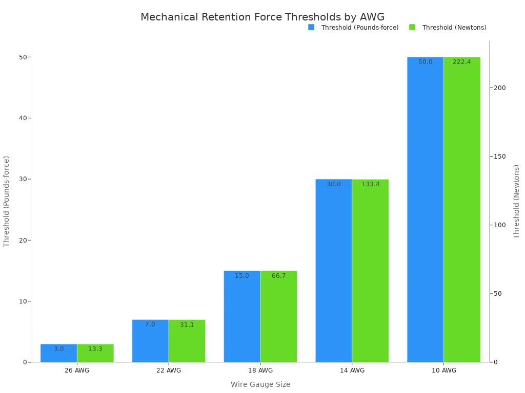
Sensors track total pull force limits. Check every pcb cable assembly well. Match these numbers to keep signals strong.
Careful planning helps each pcb layout succeed. Early prototypes need the right pcb cable assembly. This choice speeds up factory work. Teams must talk early. Engineers and harness builders share ideas. EMS partners join the plan too. Fast tests become much easier. Cables stay safe from hard wear. Early DFM tips help build custom parts. Complex box builds need these special parts. Choose standard connection hardware now. Enforce strict IPC rules always. This path brings great products every time.
FAQ
What is the main benefit of early cable assembly integration?
Early planning saves money. It stops costly redesigns. You align specs with physical limits early. This step happens before big production runs. It keeps quality high. It also speeds up building times.
How do you choose between direct soldering and pluggable headers?
Direct soldering saves money on parts. It works best for permanent links. Pluggable headers cost more at first. Yet, headers allow quick module swaps. They make factory tests easy. Pick headers for fast repairs later.
Why must you perform hi-pot tests on cable assemblies?
Hi-pot tests check wire insulation. They use high voltage to test safety. You find hidden shorts early. This stops bad system failures later. It helps your product pass safety rules. Do this before shipping to buyers.
How does wire gauge affect system performance?
Wire gauge sets power limits. It controls heat buildup inside wires. Thick wires handle heavy power well. They do not overheat easily. Good wire sizes keep signals clean. They protect your whole electronics system.
See Also
Mastering DIP Cable Assembly For Reliable Through Hole Connections
Complete PCBA Solutions From Board Fabrication To Final Testing
Understanding Circuit Board Assembly Processes For Beginners And Experts
The Ultimate Beginner Guide To Component Sourcing For PCBA
Understanding Printed Circuit Board Assembly And Its Essential Components
