Solder Joint Reliability

You need solder joint reliability to make electronics work every day. The materials and ways you use for soldering affect how long connections last. New rules, like RoHS, make you use lead-free solders. These solders need higher heat and can change how joints deal with stress and wear. You also have to do careful cleaning and quality checks to stop problems from banned substances. Solder joint reliability changes your costs and the safety of things like cars and phones.
Key Takeaways
Pick good materials and clean tools for strong solder joints. This helps the parts stick better and lowers the chance of problems.
Watch the soldering temperature closely. Not enough heat makes weak joints. Too much heat can hurt the parts.
Make SMD pads in a smart way to spread out stress. This stops cracks and helps solder joints last longer.
Check solder joints often for problems. Use machines to find issues early and keep things working well.
Use rules like J-STD-001 for the best soldering steps. This keeps electronic devices safe and high quality.
Solder Joint Reliability Factors
Material Selection
You need to choose the right materials to build strong solder joints. The type of metal for the component leads and pads affects how well the solder sticks. If you use poor-quality metals, the solder may not bond well, and the joint can fail. You also need to keep your soldering tip clean. A dirty tip can leave behind contaminants that weaken the connection. Good temperature control is important. If you use too little heat, you can create cold joints that break easily. If you use too much heat, you can damage the board or the part.
Tip: Always use proper flux to stop oxidation. Oxidation makes it hard for solder to flow and stick, which lowers Solder Joint Reliability.
Here are some key factors you should watch:
Use high-quality solder and clean tools.
Control the temperature during soldering.
Pick materials that match well with your solder alloy.
Solder Alloy Properties
The solder alloy you pick changes how long your joints last. Lead-free solders need higher heat and can form more oxides. These oxides make joints weaker. Leaded solder bends more before breaking, so it handles stress better. Lead-free solder is harder, but it can crack more easily, especially in tough places like cars or outside.
You should know that different alloys react differently to heat and stress. Some alloys resist cracking from temperature changes. Others form brittle layers that can start cracks. If you use lead-free solder, you may see more micro-cracks and defects. This happens because lead-free solder does not flow as well as leaded solder.
Lead-free solder joints can break faster under repeated heating and cooling.
The mix of metals in the solder affects how strong and flexible the joint is.
New alloys try to improve strength and reduce cracks, but they still have limits.
SMD Geometry & Stress Concentration
The shape and size of your surface-mount device (SMD) pads change how stress builds up in the solder joint. Solder mask defined (SMD) pads can focus stress at the corners where the solder meets the mask. This can start cracks, especially when the board heats up and cools down many times. If you use non-solder mask defined (NSMD) pads, the stress spreads out more, which can help the joint last longer.
Note: The way you design your SMD pads can decide where cracks start and how fast they grow.
Here is a table showing common stress points and what they can cause:
Failure Mechanism | Description |
|---|---|
Thermal Fatigue Cracking | Repeated heating and cooling causes tiny cracks and can break the circuit. |
PCB Warpage and Assembly Stress | Bending or twisting the board puts extra stress on joints, leading to early cracks. |
Pad Cratering | The area under a pad can break from sudden shocks or stress, especially in large packages. |
If you want high Solder Joint Reliability, you must design your SMD pads carefully and think about how stress will affect your joints over time.
Failure Mechanisms
Solder joints can break in different ways. You need to know these failure mechanisms to keep electronics working for a long time. The main causes are temperature changes, strong forces, and mistakes during soldering. Each cause can hurt the joint in its own way.
Thermal Cycling
When your device gets hot and then cools down, the materials inside move at different speeds. This is called thermal cycling. Solder joints feel stress every time the temperature changes. Over time, this stress can make cracks start and get bigger.
Here is what thermal cycling does to solder joints:
Mechanism | Description |
|---|---|
Crack Growth | Heating and cooling again and again makes cracks grow in the solder joint. |
Strain Amplitude | The more the solder stretches and shrinks, the shorter its life will be. |
Crack Propagation | Cracks usually follow the path with the most stress, often at the edges. |
Thermal Expansion | Different materials get bigger at different rates, which adds extra stress. |
Micro-cracks | Tiny cracks form and make the joint weaker over time. |
Stress Generation | The different rates of expansion create stress inside the solder. |
Deformation | The solder can change shape and lose its strength. |
Crack Initiation | Stress starts small cracks that can grow and break the joint. |
Functional Failure | If cracks get big enough, the device can stop working. |
Thermal cycling is slow, but it can cause big problems. For example, some solder joints last about 7,300 cycles before breaking. In real tests, some packages have survived up to 7,580 cycles before failing. If you use your device every day, these cycles add up fast.
Mechanical Overstress
Mechanical overstress happens when too much force is put on a solder joint. This can happen during assembly, shipping, or if you drop your phone. Solder joints are strong, but they can only take so much.
Here are some ways mechanical overstress can hurt solder joints:
Dropping a device can crack the solder joints inside.
Pressing too hard during assembly can break the joint.
Bending or twisting the board puts extra stress on the solder.
Accidents or rough handling can overload the joint and make it fail.
The table below shows how different types of mechanical stress affect solder joints:
Test Type | Mechanism | Failure Cause |
|---|---|---|
Random Vibration | Makes cracks grow faster at stress points | Mechanical Overstress |
You should always handle circuit boards carefully. Even small mistakes can cause cracks that grow over time. In cars, road vibrations can slowly damage solder joints. In phones, one drop can break the connection.
Solder joint embrittlement can also happen if metals like gold or palladium mix into the solder. This makes the joint more likely to crack when stressed.
Soldering Defects
Mistakes during soldering can make weak spots in the joint. These defects are common in mass production and can cause devices to fail early.
Here are some of the most common soldering defects:
Defect Type | Description |
|---|---|
Insufficient / Excess Solder | Too little solder leaves gaps; too much can cause short circuits. |
Solder Bridges | Extra solder connects two pads that should stay apart, causing shorts. |
Cold Solder Joint | Solder that does not melt or cool right forms a weak, grainy joint. |
Tombstoning | One end of a chip lifts up, usually from uneven heating, breaking the connection. |
Voids, or small pockets of trapped gas, can also form inside the solder. These voids make the joint weaker and more likely to break. In real life, medical devices need perfect solder joints to keep patients safe. In cars, a bad solder joint can make the electronics stop working. Some smart home devices have failed because of solder voids, but using better flux made them more reliable.
You need to look for these defects during production. Careful checks and good process control help you avoid problems and improve Solder Joint Reliability.
Lead-Free Solder Joint Reliability
RoHS Compliance Challenges
You face new challenges when you use lead-free solder to meet RoHS rules. These rules help protect the environment, but they also change how you build and test electronics. Lead-free solder joints react differently to heat and stress than traditional ones.
Here are some main challenges you should know:
Thermal shock from quick temperature changes puts extra stress on solder joints. This can cause cracks to start and grow.
Aging changes the inside structure of the solder. Over time, small metal layers grow and make the joint weaker.
Vibration shocks, like those in cars or planes, add more stress. This makes cracks form faster.
Temperature swings change how strong the solder is. The inside of the joint can build up stress, which lowers Solder Joint Reliability.
Tip: You should check your designs for these risks, especially if your product will face heat, cold, or vibration.
Comparative Reliability Studies
You may wonder how lead-free solder joints compare to traditional tin-lead ones. Studies show that lead-free solder has some limits you need to consider.
Lead-free solder does not bend as much as leaded solder. It breaks more easily during drop tests and thermal cycling.
These joints have lower creep resistance. They relax under stress, which can lead to cracks.
Brittle layers can form at the edges. These layers make it easier for cracks to start.
Lead-free solder can grow tin whiskers. These tiny metal hairs can cause short circuits over time.
The table below shows how leaded and lead-free solder joints perform in common tests:
Test Category | Leaded Solder | Lead-Free Solder |
|---|---|---|
Drop Test (Mobile) | ⭐️⭐️⭐️⭐️⭐️ | ⭐️⭐️⭐️ |
Vibration (Auto) | ⭐️⭐️⭐️⭐️⭐️ | ⭐️⭐️⭐️ |
Thermal Cycling | ⭐️⭐️⭐️⭐️ | ⭐️⭐️⭐️ |
Tin Whisker Risk | ⭐️⭐️⭐️⭐️⭐️ | ⭐️⭐️ |
Long-term Aging | ⭐️⭐️⭐️⭐️ | ⭐️⭐️⭐️⭐️ |
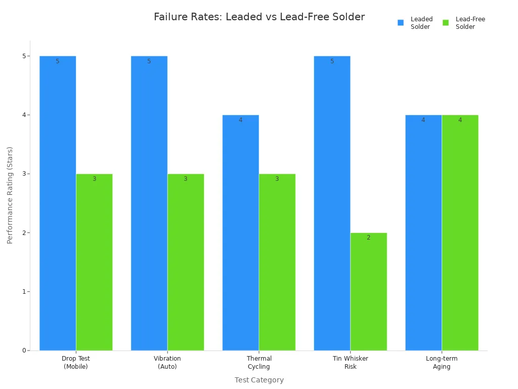
You can see that leaded solder joints usually last longer and handle stress better. Lead-free solder joints need more careful design and testing to reach the same level of Solder Joint Reliability.
Prediction & Simulation Methods
Life Prediction Models
You can use life prediction models to guess how long solder joints will last. These models help you plan for problems and make Solder Joint Reliability better. Here are some common models people use:
Coffin–Manson Life Model
Darveaux Life Model
Paris Life Model
Creep Life Model
The Coffin–Manson model looks at damage from stretching and shrinking over and over. The Darveaux model helps you see how stress affects solder joint life. The Paris model shows how cracks grow by using fracture mechanics and fatigue life. The Creep Life Model explains how solder joints slowly change shape when under steady force, especially in high heat.
These models help you know when a solder joint might break. This lets you design products that last longer and stop surprise failures.
Tip: If you use life prediction models early, you can find weak spots before making your product.
The table below shows how some methods work for guessing when solder joints will fail:
Methodology | Findings |
|---|---|
Modified Engelmaier Fatigue Model | Predicts how long lead-free solder joints last with high confidence. |
Type-I Interval Censored Data | Works well for guessing solder joint life from fast test data. |
Comparison with Minitab | Gives good estimates, showing these prediction methods work well. |
Simulation Techniques (Darveaux, PI-LSTM)
You can use simulation techniques to test Solder Joint Reliability without waiting for real failures. Finite Element (FE) simulation is a main tool. FE modeling lets you make simple models, build shapes, and use special rules for solder joints. You can use these models to see how cracks start and grow.
Darveaux simulation techniques look at stress and fatigue in solder joints. PI-LSTM is a newer way that uses machine learning to guess failures better. PI-LSTM can look at lots of data and find patterns that old models might miss.
Note: Simulation tools help you save time and money by guessing failures before they happen.
You can use both prediction models and simulation techniques to make Solder Joint Reliability better and build safer electronics.
Reliability Strategies
Design for Reliability
You can make Solder Joint Reliability better by smart design. The shape and size of solder joints matter a lot. If you change the geometry, stress spreads out more. This helps stop cracks from forming. Making buildup layers thicker in WLCSP makes joints stronger. Thicker layers mean joints break less often. Picking the right solder alloy is also important. Some alloys can handle heat and stress better.
Here are some design strategies you can try:
Change solder joint shape to spread stress.
Make WLCSP buildup layers thicker for strong joints.
Pick solder alloys that fit your needs.
Good design makes solder joints last longer and keeps devices safe.
Process Control & Inspection
You need good process control to make strong solder joints. Controlling heat during soldering stops defects from happening. Using the right flux and cooling speed makes joints better. New soldering methods, like laser and selective soldering, help control heat. These methods lower thermal stress.
Clean surfaces before soldering. Cleaning removes dirt that can weaken joints. Managing temperature and using controlled air makes soldering more steady. Automated inspection systems, like AOI and X-ray, check for defects fast. These systems find problems inside and outside, even in noisy places or with different image sizes. Deep learning helps these systems spot defects better.
AOI systems work quickly and find issues like misalignment and solder bridges. For big production runs, AOI is good, but it can miss small defects. You can use manual checks with AOI to catch every problem. Cleaning after soldering removes leftover dirt and makes joints more reliable.
Regular checks and process control help you stop failures and make Solder Joint Reliability better.
You make Solder Joint Reliability better by working on joint design. Pick the right alloy for your solder joints. Be careful when you solder parts together. Changes in temperature can cause cracks. Aging and stress from the environment can also make joints fail. Predictive modeling helps you find risks early. It lets you plan when to fix things. You should follow rules like J-STD-001 and MIL-STD-810 for good results.
Here are some easy tips:
Use good tools and materials.
Keep soldering temperature steady.
Clean and check joints after soldering.
Standard | Description |
|---|---|
J-STD-001 | Rules for soldered electrical and electronic assemblies |
MIL-STD-810 | Tests for tough conditions |
UL 746E | Certification for coatings and laminates |
FAQ
What is the most common cause of solder joint failure?
You often see thermal cycling as the main cause. Heating and cooling make solder joints expand and contract. This stress creates cracks over time.
How can you spot a bad solder joint?
Look for dull, grainy, or cracked surfaces. Cold joints may look frosty. Use magnification or X-ray tools for hidden defects.
Does lead-free solder last as long as leaded solder?
Lead-free solder usually does not last as long as leaded solder. It is harder and more brittle. You may see more cracks, especially in tough environments.
How do you improve solder joint reliability?
Use high-quality materials.
Control soldering temperature.
Clean all surfaces before soldering.
Inspect joints with AOI or X-ray.
Why do you need to clean after soldering?
Cleaning removes flux residue and dirt. This helps prevent corrosion and improves the electrical connection. Clean joints last longer and work better.
See Also
Impact of Solder Paste Quality on PCB SMT Soldering
Importance of Nitrogen Reflow Soldering in Automotive PCBA
Reliability Comparison: Through Hole vs. SMT PCB Assembly
Understanding Solder Paste Types and Components in SMT Assembly
Reasons for Component Detachment During Wave Soldering in SMT
