Low-Loss High-Speed PCB Materials Selection
Selecting low-loss high-speed PCB materials requires careful thought. You must balance electrical performance, thermal reliability, and manufacturability together. Every option has trade-offs. How do you pick the right one? This guide focuses on the decision process for high-speed PCB design. You need practical advice, not theory. Start with the material's signal integrity properties. Then compare material types. Finally, match your choice to your application. This method works for 5G systems and data centers alike. Remember, your material choice directly affects your design's success. Poor selection causes signal loss and failed prototypes. Good selection ensures reliable, high-speed designs. This PCB material selection process needs close attention. Prioritize your performance needs first. Then consider cost and fabrication limits. Your design deserves this careful approach.
Key Takeaways
Choose high-speed PCB materials with care. Balance signal quality, heat management, and price. Each option has pros and cons. Begin with what your design must do.
Dk affects how fast signals travel. Dk also affects impedance. Df measures how much energy turns into heat. Low Df is best for long, fast signal paths.
For RF circuits that work below 20 GHz, use hydrocarbon materials. For millimeter-wave circuits above 20 GHz, use PTFE materials. Do not use FR-4 for high-speed boards.
Speak with your PCB maker early. Confirm material choices with them. Check Dk values. Check Df values at the operating frequency. This prevents costly prototype failures.
Balance performance against cost. Pick top-grade materials only for key layers. Low-loss materials handle 112 Gbps speeds. A mixed stack-up cuts costs.
Key Material Properties for Signal Integrity
Two main properties guide your material choice: dielectric constant (Dk) and dissipation factor (Df). These values control impedance and loss, the two most important performance measures for any high-speed design. Dk sets how fast signals travel and the characteristic impedance. Df shows how much energy turns into heat during transmission. Together, they decide if your signal arrives clean or becomes too damaged to use.
Dk and Df Impact on Signal Integrity
Dk stability across frequency matters more than its exact number. Most materials show a small Dk drop as frequency goes up. For example, standard FR-4 measures about 4.5 at 1 GHz, while Rogers RO4350B holds near 3.48 at 10 GHz. Since impedance relates inversely to the square root of Dk, any shift changes your trace impedance. This change causes reflections and timing errors across your working range. You must use frequency-specific Dk values from supplier datasheets when running impedance simulations. Tools like Polar Si9000 let you enter these values to keep steady 50-ohm single-ended or 100-ohm differential impedance across all signal speeds.
Df directly affects signal loss over distance. Lower Df means less energy turns to heat, keeping signal strength. At 10 GHz, material grades separate clearly. Low-loss FR-4 types like Isola FR408HR or Megtron 6 range from 0.003 to 0.010. Hydrocarbon blends such as Rogers RO4350B achieve 0.002 to 0.004. PTFE materials like Rogers RO3003 reach very low values between 0.0009 and 0.002. For reference, Rogers RO4003C measures 0.0027 at 10 GHz. This ultra-low Df reduces insertion loss, making it perfect for RF and microwave circuits. Your choice depends on your frequency and distance needs.
Frequency-Dependent Dk Behavior | Impact on Impedance Consistency |
|---|---|
Dk drops slightly as frequency rises | Impedance goes up if trace geometry stays fixed, causing mismatch |
Suppliers give Dk at 1, 10, and 40 GHz | Use these values in simulations for steady impedance |
Lower Dk needs wider traces; higher Dk needs narrower traces | Adjust trace width and dielectric thickness to compensate |
Thermal and Mechanical Factors
Signal integrity matters only if your board survives its working environment. Thermal conductivity shows how well heat spreads from high-power parts. Rogers RO4350B offers 0.69 W/m/K, more than double standard FR-4's 0.3 W/m/K. This difference helps stop hot spots that lower performance over time.
Coefficient of thermal expansion (CTE) affects mechanical reliability during temperature changes. FR-4 shows anisotropic behavior: 14-17 ppm/°C in the X-Y axis but 50-70 ppm/°C through the Z-axis. Copper measures 17 ppm/°C. This mismatch, up to four times difference, causes warpage, plated through-hole barrel cracks, and delamination. PTFE laminates perform better with CTE around 10-12 ppm/°C, closer to copper. Low moisture absorption below 0.1% further reduces delamination risk. These properties make PTFE suitable for extreme environments where thermal stress repeats constantly.
Your material selection must balance electrical performance with thermal reliability. A low-loss material that fails mechanically under thermal cycling provides no benefit. Consider your power levels, ambient temperature range, and expected thermal cycles before finalizing your choice. The best design uses a material that keeps both signal integrity and structural stability throughout its service life.
Comparing Low-Loss PCB Material Types
When you compare low-loss PCB material types, three families dominate the market. Each family offers a different balance of Dk, Df, cost, and processability. The table below shows the main categories and their typical properties.
Material Family | Typical Dk (1-10 GHz) | Typical Df | Use Cases |
|---|---|---|---|
Low-/mid-loss FR-4 derivatives | ~3.6–4.2 | ~0.008–0.014 | High-speed digital up to mid-teens Gbps |
Hydrocarbon-ceramic | ~2.9–3.5 | ~0.003–0.008 | RF/microwave, 5G radios, phased arrays |
PTFE-based | ~2.1–2.6 | ~0.0009–0.003 | Microwave/mmWave, satellite, precision timing |
PTFE and Hydrocarbon: Pros and Cons
PTFE laminates, such as Rogers RO3003 and Taconic products, offer the lowest loss and most stable Dk across frequency. You can use them up to about 60 GHz. Their Dk stays between 2.1 and 2.6, and Df drops as low as 0.0009. This performance makes them the top choice for microwave, millimeter-wave, and satellite applications. However, PTFE comes with significant trade-offs. The material costs more than standard options. It requires special fabrication procedures, including cold drilling, plasma etching, and surface treatments for copper adhesion. These extra steps increase yield loss and lead time. Despite these difficulties, the electrical performance justifies the extra effort for designs above 20 GHz.
Hydrocarbon-ceramic composites, like Rogers RO4350B, offer a middle ground. They provide Dk values between 2.9 and 3.5 with Df ranging from 0.003 to 0.008. This performance suits RF and microwave applications, including 5G radios and phased arrays. The key advantage is manufacturability. Hydrocarbon materials process easily with standard multilayer PCB fabrication. You avoid the special procedures needed for PTFE. The cost is lower, and lead times are shorter. You get better yield because the material handles standard drilling and lamination without extra steps. The material bonds well with copper during standard lamination.
Aspect | PTFE | Hydrocarbon |
|---|---|---|
Cost | Higher (more expensive) | Lower (good balance between performance and cost) |
Manufacturability | Challenging, requires special procedures | Better, easier to process |
Processing Complexity | High (cold drilling, plasma etching) | Low (compatible with standard multilayer fabrication) |
Yield Loss | Higher (due to softness and adhesion issues) | Lower |
Lead Time | Longer | Shorter (compatible with standard processes) |
Other Options: FR4, PPE, and Ceramic-Filled
Standard FR-4 has a dissipation factor of approximately 0.02 at 1 GHz. This high Df leads to significant signal loss. You cannot use FR-4 for high-frequency designs above 1-2 GHz. For low-loss high-speed applications, you must look beyond FR-4. Even improved FR-4 derivatives, such as Isola FR408HR and Panasonic Megtron6 R-5775, show Df values between 0.003 and 0.010. These materials work for high-speed digital up to mid-teens Gbps.
PPE (Polyphenylene Ether) blends offer another mid-range alternative. They provide Dk around 3.4 at a lower cost than pure hydrocarbon or ceramic materials. PPE materials work well for high-speed digital designs where you need better performance than FR-4 but cannot justify the cost of PTFE. Their Dk stability across frequency makes them suitable for high-speed digital designs.
Ceramic-filled materials also fill the gap between standard and premium options. They offer Dk values ranging from 3.0 to 3.7. Their cost sits between PPE and PTFE. These materials suit applications where you need stable electrical properties without the processing challenges of PTFE. For your pcb material selection, consider these options when you need better performance than FR-4 but cannot accommodate PTFE's cost or processing requirements. Ceramic-filled materials provide good thermal conductivity for high-power designs. These materials balance cost and reliability for many mid-range applications.
The key to successful selection is matching material properties to your specific application. High-frequency materials like PTFE serve millimeter-wave designs well. Hydrocarbon blends work for 5G and RF systems. PPE and ceramic-filled options fit mid-range digital applications. Your pcb material selection process should start with your frequency and loss requirements. Match your material to your budget and fabrication needs.
Trade-Offs in Material Selection
Every choice forces you to balance competing factors. Cost, performance, and manufacturability rarely align perfectly. Your pcb material selection process starts with knowing your priorities. Each priority shifts the balance toward a different family.
When to Prioritize Performance Over Cost
Some applications need top performance no matter the price. Millimeter-wave radar systems run at 77 GHz and higher. These applications need low-loss high-speed laminates. For example, 77 GHz automotive radar for ADAS uses RO3003, a PTFE-based laminate suitable for mmWave frequencies. Standard laminates cannot handle these frequencies. Signal loss would make the product useless. You must pay the extra cost for PTFE in these cases.
The cost gap between families is large. PTFE costs much more than FR-4 or hydrocarbon blends. But the electrical performance makes it worth the money. PTFE offers low Dk and low Df for minimal signal loss. Its thermal conductivity ranges from 0.6 to 1.24 W/m·K. Its glass transition temperature goes above 200°C. These traits make PTFE good for extreme environments where reliability is key. Hydrocarbon options sit in the middle. They cost less than PTFE but more than FR-4. Their performance fits RF applications up to about 40 GHz.
In high-layer-count design, the scrap rate becomes a major cost factor. When you mix PTFE with other laminates, CTE mismatch causes warp scrap. This raises the overall scrap rate. Manufacturers add high yield compensation fees to their quotes. You must plan for this extra cost.
Manufacturing Challenges and Solutions
PTFE needs special handling during fabrication. PTFE does not bond easily with copper. Manufacturers must use plasma treatment to activate the hole wall surface. Without this treatment, the plating will not bond reliably. This causes voids and failures in plated through holes. The extra process steps increase lead time and lower yield.
Hydrocarbon options process more easily. You can use standard multilayer PCB fabrication steps. No plasma treatment is needed. The laminate bonds well during standard lamination. This compatibility reduces fabrication complexity and boosts yield. For boards with 20 or more layers, hydrocarbon options offer better stability. The CTE matches closer to copper, reducing warp and delamination risk. This improves overall reliability.
Your choice between PTFE and hydrocarbon depends on your application. For millimeter-wave above 20 GHz, you need PTFE performance. For lower frequency RF and high-speed digital, hydrocarbon options work well. The material's thermal performance also matters. Think about your operating environment carefully. Make your design decisions based on your needs. Balance your performance needs with your fabrication capabilities. Talk to your manufacturer early on your design. Discuss your selection and stack-up. Confirm that your fabricator can handle the required processes. This approach saves time and reduces prototype failures.
Application-Specific Material Choices
Your application dictates your material priorities. A 5G base station and a data center switch have different needs. You must match your pcb material selection to your specific use case. The right choice depends on frequency, power, and board complexity.
Selecting for 5G and RF Systems
5G systems operate across a wide frequency range. Sub-6 GHz bands need reliable materials with moderate loss. Millimeter-wave bands from 24 GHz to 40 GHz demand ultra-low-loss laminates. Your signal integrity depends on choosing the right grade for each frequency.
Rogers offers several material families for these high-speed applications. The RO4000 series, including RO4350B, provides a Dk of 3.48 and a Df in the range of 0.002 to 0.004. This material processes like FR-4, which keeps fabrication costs down. It works well for frequencies from 500 MHz to 40 GHz. The RO3000 series delivers lower loss. RO3003 achieves a Df in the range of 0.0009 to 0.002 with a Dk between 2.1 and 2.6. This material maintains stability up to 77 GHz, making it ideal for 5G base station power amplifiers and mmWave arrays. For premium designs above 20 GHz, PTFE laminates such as RO3003 offer Df as low as 0.0009 and Dk around 2.1-2.6, performing consistently up to mmWave frequencies.
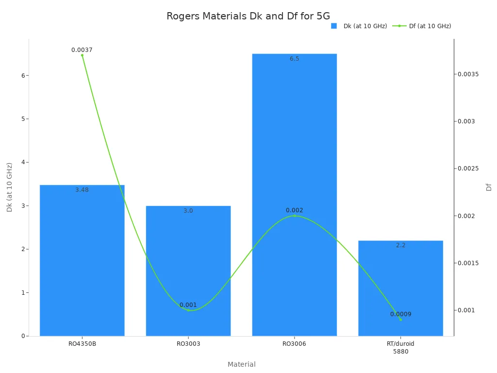
Material | Dk (10 GHz) | Df (10 GHz) | Best Use |
|---|---|---|---|
RO4350B | 3.48 | 0.002-0.004 | General RF, sub-6 GHz |
RO3003 | 2.1-2.6 | 0.0009-0.002 | mmWave, 24-40 GHz |
PTFE (e.g., RO3003) | 2.1-2.6 | 0.0009-0.002 | Above 20 GHz, phased arrays |
Your copper foil quality also affects loss. Smooth copper reduces insertion loss but may weaken adhesion. You must balance these factors during stack-up design.
Choosing for Data Centers and High-Speed Digital
Data centers push signaling speeds to 112 Gbps PAM4. These high-speed designs require materials with very low Df. The signal travels across long traces through many layers. Each layer adds loss. Your material choice determines whether the signal arrives intact.
For high-speed PAM4 signaling, you need specific material properties:
Df at the operating frequency should be very low, ideally below 0.004
Low-loss materials like Megtron 6 offer Dk between 3.6 and 4.2 with Df from 0.003 to 0.010
Ultra-low-loss materials such as Tachyon 100G provide Dk around 3.0 and Df in the range of 0.002 to 0.004
These materials support high data rates. Megtron 6 works well for most high-speed computing needs. Tachyon 100G suits the most demanding links. Your selection depends on trace length and layer count. Boards with 20 or more layers need materials with stable Dk across frequency. This stability maintains consistent impedance through every layer.
Signal loss accumulates over distance. A long trace on a standard material loses more signal than a short trace. You must calculate your maximum trace length and choose your material accordingly. Your design also needs careful attention to copper surface roughness. Smoother copper reduces loss but costs more. Your fabricator can help you select the right copper type for your high-speed applications.
The pcb material selection process for data centers balances performance with cost. You cannot use premium materials everywhere. You might use ultra-low-loss material only for critical high-speed layers. Standard low-loss material works for less demanding signals. This hybrid approach controls cost while maintaining signal integrity.
Best Practices and Pitfalls
Avoiding Common Mistakes in Material Choice
Several common mistakes cause field failures in your boards. You must spot these traps early in your pcb material selection process.
Using FR-4 with variable Dk causes impedance drift. This leads to signal integrity failures during operation. FR-4's high Df severely weakens high-frequency signals. This degrades data eyes and causes intermittent errors. CTE mismatch between laminate and copper causes via cracking and pad lifting during thermal cycling. This results in open circuits over time. Over-specifying laminate performance by choosing exotic low-Dk materials when not needed drives up cost without benefit. Under-specifying risks field failures.
Moisture absorption also affects your material's long-term reliability. Water has a high dielectric constant. Absorbed moisture raises the effective Dk of the laminate. A small change in Dk causes significant shifts in trace impedance. Standard FR4 absorbs more moisture than PTFE, which typically has very low moisture absorption (below 0.1%). This difference matters for controlled-impedance work.
The material's inert nature resists moisture absorption and chemical degradation. This ensures long-term stability in harsh environments.
Working with Manufacturers for Optimal Results
You must consult with PCB fabricators early in your design process. Start the conversation before you finalize your stack-up. Share your frequency and loss requirements with them. Ask for their recommended materials that match your needs.
Request material datasheets from your fabricator. Verify the Dk and Df values at your operating frequency. Run impedance simulations before you commit to a stack-up.
Confirm that your fabricator can handle the required processes. Some materials need special procedures. PTFE requires plasma treatment for copper adhesion. Hydrocarbon materials process with standard fabrication steps. Knowing these limits early prevents delays.
You also benefit from discussing surface roughness. Smoother copper reduces loss but may weaken adhesion. Your fabricator can help you select the right material for your application.
Following high-speed design best practices improves your board's reliability. A good working relationship with your manufacturer helps you avoid costly mistakes. Your selection of material and copper directly affects performance and production success. Consider electromagnetic compatibility requirements early in the process.
No one material works for all high-speed designs. Your pick depends on frequency, heat, and cost. You must balance Dk, Df, heat flow, and how easy it is to make the board. Each factor changes how your PCB works and lasts.
Begin choosing your PCB material early. Talk to material suppliers and board makers before you set your stack-up. They check that your choices match what can be made. This step stops expensive mistakes on test boards.
New materials give better choices. Liquid crystal polymer (LCP) and advanced ceramics offer stable dielectric properties at mmWave frequencies and low moisture absorption. These options cut loss and boost long-term reliability for 5G and AI data centers. Your next design can use these advances to improve signal quality and copper trace performance. Smooth copper surfaces also reduce loss in these new laminates.
FAQ
What is the difference between Dk and Df?
Dk sets how fast signals travel and the impedance. Df tells how much energy turns into heat. Lower Df means less signal loss. For high-speed PCB design, you need stable Dk across all frequencies and low Df.
Can I use standard FR-4 for high-speed PCBs?
No. Standard FR-4 has a high Df of about 0.02 at 1 GHz. This causes a lot of signal loss above 1-2 GHz. For high-speed PCB needs, you must use low-loss materials like hydrocarbon or PTFE.
What material works best for 5G millimeter-wave circuits?
PTFE-based laminates like Rogers RO3003 are best. They have Df below 0.002 and stable Dk up to 77 GHz. These materials keep signal integrity at mmWave frequencies above 20 GHz.
How do I balance cost and performance in material selection?
Pick your material based on your frequency needs. Use hydrocarbon for RF and microwave applications up to 40 GHz. Use PTFE for millimeter-wave circuits above 20 GHz. This way to choose materials controls cost and makes the board more reliable.
What are common mistakes in PCB material selection?
Ignoring moisture absorption, overlooking CTE mismatch, and using FR-4 for high-speed boards. These errors cause impedance drift, via cracking, and signal loss. Check material datasheets to make sure your PCB is reliable before you finish your design.
See Also
Choosing Appropriate PCB Substrates For Surface Mount Assembly
Designing PCBs For Efficient SMT Manufacturing And Processing
Essential Raw Materials Required For PCBA Manufacturing Processes
Selecting The Right PCBA Partner For Your Specific Requirements
