The Definitive Guide to High TG PCB Material Testing Before Production
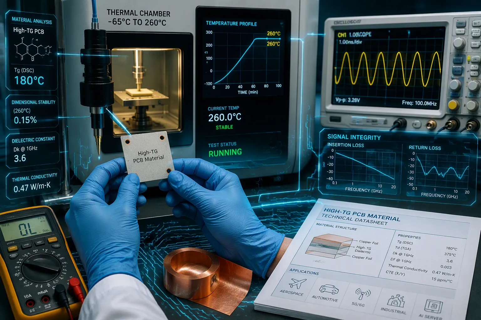
Cars, planes, and LED lights need circuit boards that work in very hot conditions. If you skip testing before making them, they can break in the field. Which tests are required? How do you run them? What scores show your high tg pcb is ready? You need answers before you start production.
Your high tg pcb design must pass heat checks, strength checks, and reading the results. These tests follow IPC-4101 and IPC-6012 rules. You must check that your high tg materials meet the specs. A high tg pcb prototype needs careful test steps. Your circuit fails early without proper checks. The board must handle heat stress. You cannot guess if it is reliable; you must test it.
Key Takeaways
High Tg PCB materials handle heat better than regular FR-4, so they stop bending and peeling apart.
Before production, run heat tests like DSC, TMA, and TGA to check Tg, CTE, and Td.
Pass structural tests like T260/T288 and solder float to make the assembly survive.
Make sure your high Tg PCB meets IPC-4101 and IPC-6012 standards so it works reliably.
Test each material batch to prevent failures in the field and safeguard your reputation.
Why High Tg PCB Materials Testing Matters
High Tg materials resist heat better than standard laminates. Standard FR-4 has a glass transition temperature around 130-140°C. High tg fr4 starts at 170°C and often reaches 180°C. This difference matters because a board softens when it exceeds its Tg. A high tg pcb stays rigid near hot engines, bright LEDs, and power electronics. You gain high tg benefits like reduced warping, stronger layer bonding, and fewer thermal failures. The material's higher modulus above Tg prevents barrel cracking in vias under vibration. Stable resin flow during lamination ensures uniform prepreg bonding, which directly reduces delamination risk.
Problem with Low-Tg PCB | How High-Tg PCB Solves It |
|---|---|
Thermal Deformation: Low-Tg boards soften under heat, causing warping or bending. | High-Tg material remains stable at elevated temperatures, preventing deformation and maintaining board integrity. |
Delamination: Excessive heat separates layers of multilayer PCBs, damaging internal circuits. | High-Tg PCB offers stronger bonding between layers, reducing the risk of delamination. |
Reduced Electrical Reliability: Softening substrate degrades signal transmission, especially in high-frequency circuits. | High-Tg materials ensure consistent electrical performance even under high thermal stress. |
You must verify incoming materials before production. A high tg pcb prototype needs confirmation that the laminate actually meets its rated Tg. The IPC-TM-650 method 2.4.25 specifies differential scanning calorimetry (DSC) for this measurement. Skipping this verification creates serious risks. Consider what happens without proper testing:
Failure Symptom (Field/Assembly) | Missing Test Parameter | Consequence if Untested |
|---|---|---|
High fall-out with internal failures at board level | Thermal Decomposition Temperature (Td) | Catastrophic laminate breakdown during lead-free reflow (up to 260°C) |
Numerous delamination pockets | Time-to-Delamination (T260/T288) | Material cracks or delaminates before assembly dwell time completes |
Inner layer connection breaks | Coefficient of Thermal Expansion (CTE) | Z-axis expansion mismatch causes stress, cracking, and loss of interconnect reliability |
Overall laminate breakdown | Combined thermal properties (Td, CTE, T260/T288) | Relying solely on Tg (e.g., 170°C) fails to predict real-world lead-free assembly survival |
Defining High Tg and Reliability Benefits
High tg fr-4 offers a clear advantage over standard materials. Standard FR-4 has a Tg around 130-150°C. High tg options like Isola FR370HR reach 180°C. Some high tg laminates go even higher. Polyimide reaches up to 300°C. Ceramic substrates handle up to 1000°C. You choose based on your application's heat exposure.
High tg materials also reduce z-axis expansion. High tg fr4 has a z-axis CTE of 50-60 ppm/°C compared to 70 ppm/°C for standard FR-4. This reduced expansion minimizes stress on vias and solder joints during thermal cycling. Exceeding the Tg of standard FR-4 by just 10°C can increase its CTE by 300%. High tg materials prevent this by maintaining structural integrity at higher operating temperatures. You get a circuit that survives thermal cycling without cracking.
Key Industry Standards for High Tg Materials
IPC-4101 and IPC-6012 govern high tg pcb materials. IPC-4101E specifies Tg requirements for different slash sheets. IPC-4101/126 and /129 require Tg of at least 170°C and Td of at least 340°C. IPC-6012 Class 3 sets stricter rules for high reliability applications.
Standard | Parameter | High Tg Requirement |
|---|---|---|
IPC-4101E | Glass Transition Temperature (Tg) | 170–180°C |
IPC-6012 Class 3 | Minimum Average PTH Copper Thickness | 25 μm |
IPC-6012 Class 3 | Solder Float Stress | 288°C for 10 seconds |
IPC-6012 Class 3 | T288 Time to Delamination | ≥15 minutes |
Maintaining a 20–30°C thermal margin prevents the substrate from entering its glass transition phase during prolonged heat exposure.
You must test high tg pcb materials against these standards. A high tg pcb prototype that passes these checks will perform reliably in the field. Circuit boards that fail testing cost you money through recalls and warranty claims. Testing protects your reputation and your bottom line.
Thermal Stability Test for High Tg Materials
Thermal analysis is the core of checking high tg pcb materials. You need three different tests to fully understand how a laminate reacts to heat. Each test looks at a separate property, and together they give you a full view of thermal stability. You cannot use just one test to confirm the board is ready for production.
Tg Measurement by DSC (IPC‑TM‑650 2.4.25)
Differential scanning calorimetry (DSC) measures the glass transition temperature of your high tg pcb materials. This test follows the IPC-TM-650 2.4.25 method. The process needs three separate heating steps to get accurate results.
First, you heat the sample to about 10°C above the expected Tg1, then cool it right away. This first step sets a steady baseline and removes false signals from stress or moisture. Second, you heat the sample again to either 175°C or 190°C, based on the epoxy resin type. You keep the sample at that temperature for 15 minutes, then cool it back to the start. Third, you do a final heat scan to measure Tg2. You then use Tg1 and Tg2 to find the cure factor or delta Tg.
The pass mark for high tg fr4 requires a Tg of at least 170°C. Standard FR-4 usually measures 130-140°C. This gap matters because a board softens when it goes past its Tg. Your high tg pcb prototype must show this higher transition point before you start production.
Technique | Primary Measurement | Key Reliability Parameter |
|---|---|---|
DSC | Heat capacity change at Tg | Glass transition temperature (Tg) |
TMA | CTE change at Tg | Z-axis expansion stability |
TGA | Mass loss with heating | Decomposition temperature (Td) |
CTE and Decomposition via TMA and TGA
Thermomechanical analysis (TMA) measures size changes in your high tg laminates as temperature goes up. This method directly measures the coefficient of thermal expansion (CTE). High tg fr-4 should show a z-axis CTE of 45-55 ppm/°C below Tg. Standard FR-4 runs higher at 60-70 ppm/°C. Lower z-axis expansion reduces stress on plated through-holes and improves thermal fatigue life. TMA also finds the slope change in the expansion curve at Tg, giving you a second check of the glass transition point.
Thermogravimetric analysis (TGA) measures weight loss as you heat the sample. This test finds the decomposition temperature (Td). High tg fr4 should show a Td of at least 340°C. Standard FR-4 breaks down around 310-320°C. A higher Td stops chemical breakdown during lead-free soldering, which can reach 260°C. TGA also checks material purity by showing unexpected weight loss events.
Criterion | Standard FR-4 | High-Tg FR-4 Threshold |
|---|---|---|
Glass Transition Temperature (Tg) | 130–140 °C | ≥170 °C |
Decomposition Temperature (Td) | 310–320 °C | ≥340 °C |
Z-Axis CTE (below Tg) | 60–70 ppm/°C | 45–55 ppm/°C |
T288 Time to Delamination | ~5 minutes | 15+ minutes |
You must run all three thermal stability tests on every new batch of high tg pcb materials. A high tg pcb prototype that passes DSC, TMA, and TGA checks will survive repeated reflow cycles and long heat exposure. Skipping any single test leaves a gap in your reliability data. The thermal stability test suite costs time upfront, but it saves you from major field failures later. Your circuit depends on these measurements to work as designed.
Structural Integrity Tests for High Tg PCBs
Thermal stability tests check the basic properties of your high tg pcb materials. Structural integrity testing shows the material can handle assembly and last a long time. High tg materials need higher heat during making and longer hardening times. This affects the board's dimensional stability. Makers impose stricter limits on warpage and bending for high tg pcb circuit boards. You must test these physical limits before production. This is an important step for any high tg pcb design. A high tg pcb prototype must pass these checks to prove it is reliable.
T260/T288/T300 and Solder Float Tests
These tests check how well the material handles very hot soldering. The T260 and T288 tests look for layer separation at 260°C and 288°C respectively. The pass condition is no layer separation after a set time at that heat. The solder float test is a direct practice. You float a board sample on liquid solder at 288°C for 10 seconds. The pass criteria are no hole wall damage and no layer splitting after inspection. A high tg fr-4 sample must show no damage to hole walls and no splitting of layers. This test confirms the high tg material strength. You need this for reliable high tg pcb making. A high tg pcb prototype must pass the solder float test before going to assembly. This is very important for any high tg pcb.
Test / Parameter | Acceptance Criterion |
|---|---|
Solder Float Test | Board sample floats on liquid solder at 288°C for 10 seconds; zero hole wall damage and no layer splitting after inspection |
Copper Peel Strength | Must be over 2 lb/in to prevent layer peeling |
Thermal Cycling | System heat switched between -40°C and +125°C; board must survive without delamination or cracking |
Microsectioning | Visual inspection of inner layers shows no tiny barrel cracks, gaps, or hidden internal voids |
Material Tg Rating | High Tg laminates must maintain resin bond integrity and reduce Z-axis expansion under 260°C peak reflow heat |
Thermal Cycling and Mechanical Fatigue
The thermal cycling test checks if the board can handle repeated temperature changes. You switch the system heat between -40°C and +125°C. The board must survive without delamination or cracking. High tg materials resist creep and wear better. High tg fr4 laminates with a Tg over 170°C keep their mechanical strength during this test. They reduce the stress on plated through-holes. This test is important for the final high tg board physical quality. A high tg pcb prototype that passes this test will survive real-world conditions. Your circuit depends on this reliability. You must use these tests in your production quality control.
Parameter | Typical Value / Range |
|---|---|
Temperature Range | -40°C to +125°C |
High Tg Laminate Recommendation | Tg > 170°C |
Interpreting Test Results and Acceptance Criteria
After you run the thermal and structural tests, you must check the results against clear pass/fail rules. These rules come from IPC-4101 slash sheets and IPC-6012 Class 3 requirements. The standards list the lowest values your high tg pcb must hit before production. You cannot rely on guessing. Each test has a specific limit that tells a good board apart from a possible failure.
Pass/Fail Thresholds for Tg, CTE, and Td
The glass transition temperature (Tg) must be at least 170°C per IPC-4101/126 or /129. You also need a safety buffer of 20-30°C above the hottest temperature your circuit will see. This buffer keeps the high tg pcb stiff during peak heat. The decomposition temperature (Td) must be at least 340°C. TGA measures the decomposition temperature (Td) as the point where the resin loses mass, indicating the onset of decomposition. The z-axis CTE is also a key value. The table below compares standard FR-4 and high tg fr-4:
Parameter | Standard FR-4 | High Tg |
|---|---|---|
Z-axis CTE below Tg | 60-70 ppm/°C | 45-55 ppm/°C |
Tg threshold | 130-140°C | ≥170°C |
The total z-axis expansion must be controlled to prevent via and solder joint stress. The T288 delamination time must be 15 minutes or more. These limits directly affect how reliable your circuit will be. If any value falls short, the material fails the test. A high tg pcb prototype must meet these limits. You need to check these limits on every new batch of high tg materials.
Correlating Test Data to Field Reliability
Test data from DSC, TMA, TGA, and T288 gives a strong indication of how the board will perform in the field. High Tg materials with a Tg of 170°C or higher keep the board in a steady, low-expansion state across a broader temperature range, reducing Z-axis expansion stress on plated vias. This directly lowers the risk of delamination and improves multilayer stackup registration. Your circuit boards benefit from lower z-axis expansion, which reduces stress on vias and solder joints. A high tg pcb prototype that passes thermal cycling will likely do well in the field. The mix of high Tg, low CTE, and high Td ensures that your board resists warping, layer separation, and chemical breakdown. A high Td stops chemical breakdown during soldering, so the material does not degrade permanently. You must record all test results for traceability and to meet IPC-6012 Class 3 high reliability standards. This record helps you confirm that each batch meets your specs.
You now understand the three critical test categories. Thermal analysis uses DSC, TMA, and TGA to verify your high tg pcb material properties. Structural integrity tests like T260/T288 and solder float confirm assembly survival. Result interpretation ties everything to IPC standards.
Testing per IPC-4101 and IPC-6012 remains the only way to guarantee high tg materials performance. Follow this checklist before production:
Request material data sheets with Tg, CTE, Td, and T260/T288 values
Perform in-house validation on every incoming batch
Document all results for traceability and high reliability compliance
Your high tg pcb prototype deserves these checks. Your circuit depends on them. Before you commit to production, run these tests—your product's reliability depends on it. Contact our team for a downloadable test checklist.
FAQ
How long does the whole testing process take?
The testing process can take several days to weeks, depending on the tests required. DSC, TMA, and TGA runs are relatively quick. T260/T288 tests require more setup time. Thermal cycling is the longest test. Plan your schedule to fit this.
Can I skip testing if my supplier gives me a datasheet?
Do not skip checking. Supplier datasheets give reference numbers, not promises for your exact batch. Your high tg pcb prototype needs its own confirmation. Run your own tests on every batch you get. This step saves your production schedule and stops expensive field failures.
What happens if my material fails the T288 test?
A failed T288 test means your laminate cannot handle long soldering heat. You must reject that batch. Ask your supplier for a replacement with better heat performance. Your high tg pcb design needs materials that meet the 15-minute minimum. Do not use low-quality laminates.
Does a higher Tg always mean a better board?
Not always. Higher Tg values help with heat resistance, but other things matter too. Your circuit needs balanced properties like low CTE and high Td. A board with great Tg but bad decomposition temperature will still fail under lead-free soldering. Look at the whole heat profile, not just one number.
How do I write down test results for rules?
Record every measurement from each test run. Include the date, who ran the test, what equipment was used, and the raw data. Keep this info with your batch records. Your high tg pcb prototype paperwork should link back to specific material lots. This meets IPC-6012 Class 3 rules and helps with quality checks.
See Also
Essential Raw Materials Required for PCB Assembly Manufacturing
Comprehensive Overview of PCBA Fabrication Steps for All Skill Levels
Five Sophisticated Inspection Techniques for Professional Thru-Hole PCB Assembly
Fundamental Specifications for Circuit Boards in Surface Mount Technology Production
Choosing Appropriate Substrate Materials for Surface Mount Assembly Processes
