Rogers PCB vs FR-4: Performance Comparison & Use Cases
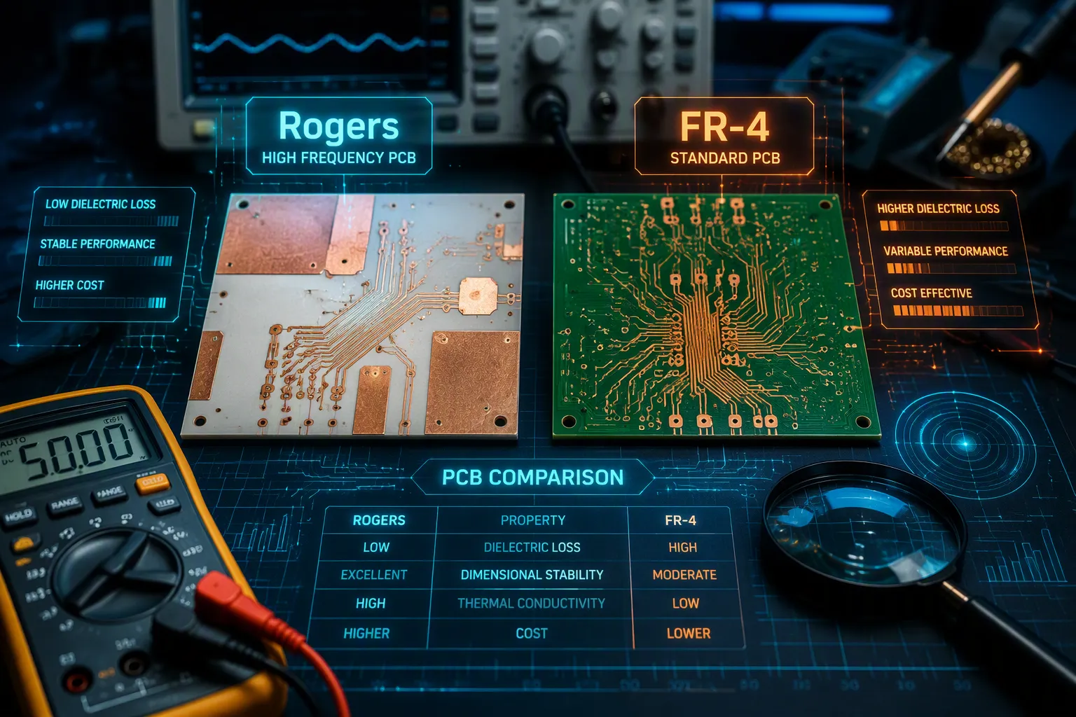
Choosing the right printed circuit board material can feel overwhelming. You face a big choice between two popular options. Rogers PCB gives better high-frequency performance, but it costs a lot more. FR-4 stays budget-friendly, yet it has trouble with signal quality past certain limits. In fact, FR4 works reliably up to about 1-2 GHz, but beyond that signal loss becomes significant. Rogers handles high frequency far beyond that range. This rogers pcb vs fr-4 comparison looks at key electrical, thermal, and cost factors. You will learn which material fits your project best. We will explore the performance differences between fr-4 vs. rogers pcb. We will also talk about high-speed digital designs and general-purpose uses. An fr4 pcb works well for simple, low-cost projects. By the end, you can make a smart choice for your next project.
Key Takeaways
Rogers PCB materials work well in high-frequency and RF applications because they have a stable dielectric constant and lose very little signal.
FR-4 is a good, low-cost choice for designs that run below 10 MHz, but it has trouble keeping signals clean when speeds go above 1-2 GHz.
Rogers handles heat better and resists moisture more, which makes it more reliable in tough conditions.
Although Rogers costs more at first, it can lower the total system cost by allowing smaller parts and preventing the need for redesigns.
Pick Rogers for high-speed digital, 5G, radar, and satellite tasks, and pick FR-4 for simple, low-cost projects.
Rogers PCB vs FR-4: Material Basics
Learning what your PCB is made of helps you know why these materials act so differently. The base material controls everything from signal quality to how long the board lasts. Let's look at what makes each material special.
Rogers PCB Material Composition and Properties
Rogers PCB material uses special composites built for tough RF work. Unlike regular options, these laminates often have ceramic-filled PTFE or thermoset hydrocarbon compounds. You won't find the usual glass fiber weave in the middle of these boards. Instead, makers build them with ceramic fillers that give stable electrical properties.
The RO4000 series is a popular choice among high-performance substrates. These materials have a dielectric constant around 3.38 to 3.48 at 10 GHz, depending on the grade. They also offer above-average thermal conductivity in the range of 0.6 to 0.8 W/m/°K. This means heat moves away from parts faster, which helps your design run cooler.
Moisture resistance gives Rogers another edge. These laminates soak up only 0.02% to 0.08% moisture. That low absorption keeps dielectric performance steady even in humid places. Your signals stay clean because the material's properties don't change with weather.
FR4 Substrate: Composition and Typical Characteristics
FR4 takes a completely different path. Standard FR4 is made of woven glass cloth soaked in epoxy resin. Copper foil is pressed onto one or both sides to create the paths for electricity. This glass-and-epoxy mix has been used in electronics for many years.
The dielectric constant of FR-4 ranges from 4.2 to 4.8 at 1 GHz. That number changes based on weave style and resin content. You also need to know about the glass transition temperature. Standard FR-4 laminates have a Tg around 130 to 140°C. Above this temperature, the material gets soft and loses its strength.
Moisture absorption is a bigger problem with FR4. Standard grades soak up 0.1% to 0.2% moisture. That sounds small, but it affects dielectric performance over time. In humid conditions, absorbed water changes the material's electrical properties. Your signal quality suffers as a result.
Standard FR4 is made of woven glass cloth soaked in epoxy resin. In contrast, Rogers PCB materials often use ceramic-filled PTFE or thermoset hydrocarbon composites built specifically for RF uses.
This basic difference in build explains why the rogers pcb vs fr-4 performance gap exists. When you compare fr4 pcb options against Rogers, you are really comparing two different material ideas. FR-4 gives proven, low-cost reliability for simple circuits. Rogers delivers precision for uses where signal quality matters most.
Electrical Performance: FR-4 vs. Rogers PCB
The electrical behavior of your PCB material determines how well your signals travel. Two factors matter most: dielectric constant stability and dissipation factor. These properties control signal integrity and frequency limits.
Dielectric Constant Stability and Signal Integrity
The dielectric constant (Dk) measures how much a material stores electrical energy. A stable Dk means your signals arrive on time and without distortion. FR-4 struggles with stability. Its Dk changes with temperature and frequency. In the 0-70°C range, FR-4's permittivity can shift by up to 20%. This change causes a 10% variation in line delay. Your timing budget suffers when this happens.
Frequency also affects FR-4's Dk. At 1 MHz, the dielectric constant sits around 4.5-4.8. As frequency climbs to 10 GHz, that value drops to roughly 4.0-4.3. That represents a 10-20% reduction. For high-speed designs, this variation creates impedance mismatches. Signals reflect, data corrupts, and your board fails to meet specifications.
Rogers PCB materials take a different approach. Their Dk ranges from about 2.2 to 3.5, depending on the grade. More importantly, this value stays consistent across temperature swings and frequency changes. A stable Dk means predictable impedance. Your high-speed digital signals maintain their shape and timing. This consistency proves critical for high-speed pcb designs where every picosecond counts.
Material | Typical Dk | Dk Stability |
|---|---|---|
FR4 | Approx. 4.3–4.5 | Varies significantly with temperature/frequency |
Rogers | Approx. 2.2–3.5 | Very stable and consistent |
Dissipation Factor and High-Frequency Limitations
The dissipation factor (Df) tells you how much signal energy turns into heat. Lower Df means less loss. FR-4 has a Df around 0.02 at 1 MHz. That number climbs as frequency increases. At 1 GHz, the loss becomes severe. High-frequency signals attenuate quickly, crosstalk increases, and timing errors appear.
FR4 can handle low- to mid-frequency applications, but it is not ideal for high-frequency or RF designs. Materials like PTFE are better suited for minimizing signal loss at higher frequencies.
FR-4 works reliably from a few MHz up to roughly 1-2 GHz. Beyond 2 GHz, material loss increases significantly. This limit comes from the dielectric constant rising at high frequencies, which slows signal transmission and boosts attenuation. For 5G systems, Wi-Fi 6/7, radar, and satellite links, standard FR4 fails to deliver acceptable performance. An fr4 pcb simply cannot handle these demanding conditions.
Rogers PCB materials offer a much lower dissipation factor, which significantly reduces signal loss at high frequencies. You can push operating frequencies into the microwave range without worrying about excessive loss. This high-frequency performance makes Rogers the preferred choice for RF amplifiers, antennas, and high-speed digital data transfer.
FR-4 is a cost-effective choice for multilayer PCBs and works well for frequencies from DC to low GHz.
For high-speed digital signals above 1 GHz, the choice becomes clear. FR-4's high dielectric loss causes excessive attenuation, crosstalk, and timing errors. Rogers eliminates these problems. Your high-speed data rates stay clean, your signal integrity holds, and your design meets its performance targets. This becomes critical when you push toward high frequency operation.
The performance gap between these materials grows with frequency. At low frequencies, FR4 works fine. Past 1-2 GHz, Rogers becomes necessary. Understanding this difference helps you choose the right material for your application.
Thermal and Mechanical Comparison
Heat and water are two big problems for PCB materials. Your board needs to take heat away from parts. It also needs to stop water damage in wet places. These things affect how long the board lasts and how well it works.
Thermal Conductivity and Heat Management
Heat can ruin electronics. Each part makes some heat when it runs. Your PCB material must pull that heat away from delicate parts. Thermal conductivity tells us how well a material moves heat. Higher numbers mean better heat spreading.
Rogers PCB materials are great at this. Ceramic‑filled laminates move heat much faster than normal options. The table below shows typical numbers for three Rogers products:
Product | Thermal Conductivity (W/m-K) |
|---|---|
TC350 | 0.72 |
TC350 Plus | 1.24 |
TC600 | 1.1 |
These numbers show a clear benefit. Heat moves through Rogers materials fast. Your parts stay cooler. You need smaller heatsinks or fewer thermal vias. This makes your design simpler and saves space.
FR‑4 does not work as well. Standard fr4 has much lower thermal conductivity. Heat builds up around high‑power parts. You must add extra copper planes or thermal vias to fix this. These additions raise cost and make things complex. For high‑power designs, this difference is very important.
Moisture Absorption and Reliability
Water harms PCB materials. Water that gets in changes electrical properties. It also causes swelling and peeling over time. Your board's reliability depends on stopping water.
FR‑4 takes in more water than Rogers materials. Standard fr‑4 shows a moisture absorption rate of 0.10% to 0.20% by weight. That water changes the dielectric constant. Signal quality drops. In wet outdoor areas, this problem gets worse.
Rogers laminates stop water much better. Tests show absorption rates of only 0.02% to 0.08%. That is a big improvement over fr‑4. Your signals stay stable even in wet conditions. The dielectric properties stay the same. This reliability makes rogers pcb the better choice for outdoor gear, car systems, and factory use.
The difference between these materials affects your design choices. For dry indoor places, fr4 works fine. For tough conditions, Rogers gives you peace of mind. Think about your working environment carefully before choosing.
Cost Analysis: Rogers PCB Material vs. FR4
When you look at costs, the price gap between these two materials is very clear. Price affects many choices in PCB design. You need to know the numbers before you decide.
Upfront Cost Differences
The price difference is large. FR-4 is significantly cheaper than Rogers materials. The exact cost depends on the specific grade and quantity, but Rogers can cost several times more than FR-4. PTFE-based materials are especially expensive. These premium Rogers materials also need special processing, such as plasma desmear, which adds to the cost.
You might ask why anyone would pay so much. The answer is what you get for the money. FR-4 gives you a cheap, trusted substrate for simple circuits. But it lacks the electrical stability needed for hard work. You pay less now, but you may face limits later.
For high-frequency designs, the upfront cost of Rogers is part of a bigger picture. You are not just buying a piece of material. You are buying predictable performance, stable impedance, and reliable signal integrity. These things matter when your design goes past 1 GHz.
Cost-Performance Tradeoffs for High-Frequency Designs
The real cost look goes beyond the price per square foot. You must think about total system cost. This includes parts, assembly, testing, and possible re-designs. This Rogers PCB vs FR-4 comparison shows why upfront cost is only part of the story.
Using a low-loss Rogers material in a power amplifier can reduce insertion loss significantly compared to FR-4. This reduction may allow the use of a smaller, less expensive power amplifier chip, offsetting the higher material cost. In volume production, the savings on components can balance the added PCB cost.
The same idea works for 5G mmWave antenna designs. Antenna feed networks and beamforming circuits suffer from signal loss. FR-4 adds too much loss at these frequencies. You need bigger amplifiers or more power to fix that. That raises component cost and power use. Rogers avoids this problem. The higher material cost is balanced by savings elsewhere.
You can also use hybrid builds to manage cost. These boards combine high-performance signal layers with FR-4 structural layers. You get the RF performance you need while significantly cutting total material cost compared to an all-premium build. This method works well for multilayer boards where only some layers need high-frequency properties.
The cost versus performance tradeoff becomes clear at higher frequencies. Below 1 GHz, an FR4 PCB usually works fine. The lower material cost makes sense. Above 1 GHz, signal loss in the cheaper substrate forces you to over-design your system. You need bigger parts, more power, and better cooling. These costs add up fast. Rogers avoids this problem. The material cost is higher, but the total system cost can be lower.
For high-speed digital designs, the same logic holds. Signal integrity is critical. Regular FR4 introduces timing errors and jitter at high data rates. Rogers keeps signals clean. You avoid costly re-designs and debugging cycles. The premium materials pay for themselves through reduced development risk.
Think about the total cost of your project, not just the PCB material. Factor in component costs, assembly yield, testing time, and field reliability. For high-frequency applications, Rogers often gives a better overall value. The upfront premium is real, but the long-term savings are big.
Application Use Cases: When to Choose Each
The material you pick depends on how fast your signals run and what your design needs. Each option works well for different jobs. Let's see where each one fits best.
High-Frequency and RF Applications
Rogers PCB materials are the right pick for high-frequency and RF work. This includes radar systems, 5G base stations, satellite links, and fast digital circuits. The steady dielectric constant and low dissipation factor make Rogers a must-have for these tough jobs.
Radar systems need different materials based on their frequency range.
5G base station antennas have strict low-loss requirements. This tight limit is the main reason engineers pick low-loss materials like Rogers, because standard FR-4 cannot always hit this performance level.
Fast digital designs also gain from these materials. When your data rates go above 1 GHz, keeping signals clean becomes vital. The low dissipation factor keeps your signals clear. You avoid timing mistakes and data errors. For high-speed work, this dependability matters a lot.
Rogers also handles important jobs in aerospace and defense. These fields need steady electrical properties in rough conditions. The low moisture pickup and good heat flow support these demanding settings.
General-Purpose and Low-Frequency Designs
FR-4 stays the smart pick for everyday electronics. Your working frequency should stay below 1-2 GHz for dependable operation. This covers most consumer gadgets, simple logic circuits, and budget-focused projects.
An FR4 PCB works well for microcontroller boards, power supplies, and audio gear. These jobs do not need the high-frequency power of Rogers. The lower price of FR4 makes sense when your signals stay at low frequencies. You can also use FR4 for simple designs that do not need top-tier materials.
You can use FR-4 for many standard builds. LED drivers, sensors, and basic control boards all run fine on this material. The dielectric constant shifts do not matter at these speeds. Your signal quality stays good enough without premium materials.
The cost benefit of FR-4 shows up in large production runs. When you make thousands of boards for consumer products, every dollar counts. FR-4 gives you solid performance at a much lower price.
For high-speed and RF jobs, the answer is clear. Rogers gives you the results you need for fast and radio-frequency work. But for standard low-frequency tasks, FR-4 provides everything you need without the high price tag.
Your choice between Rogers PCB and FR-4 depends on signal speed and money. Rogers is better for high-frequency, low-loss, and hot work. FR-4 is still cheap for normal electronics. If your signal speed goes above 1-2 GHz, or you need steady dielectric performance, pick Rogers. If not, FR-4 works fine. The FR-4 vs. Rogers PCB comparison shows that fast designs need top-quality materials. For 5G systems and RF circuits, this choice matters a lot. Rogers gives steady performance where FR-4 materials fail. The value of Rogers gets better at higher speeds. You skip signal loss and expensive redesigns. Think about what your project really needs before you decide.
FAQ
Can I use FR‑4 for RF designs?
You can use FR‑4 for low‑frequency RF work under 1‑2 GHz. Beyond that, signal loss gets very bad. The dissipation factor rises fast with frequency. Your signals get weak and distorted. For reliable RF work above 2 GHz, pick Rogers instead.
Why does Rogers cost so much more than FR‑4?
Rogers uses special ceramic‑filled compounds. These materials need careful processing and tighter quality checks. FR‑4 uses common glass and epoxy. The difference in making them causes the price gap. You pay for stable electrical properties and steady performance.
What is a hybrid PCB build?
A hybrid board uses both materials. You use Rogers layers for high‑frequency signal paths. FR‑4 layers take care of support and power distribution. This method can significantly reduce material costs. You get Rogers performance where it matters most.
Does moisture really affect PCB performance?
Yes, water changes dielectric properties. FR‑4 soaks up 0.1 to 0.2 percent water by weight. That water changes signal speed and impedance. Rogers soaks up only 0.02 to 0.08 percent. In damp places, this difference affects reliability and signal quality.
How do I choose between Rogers and FR‑4?
Look at your operating frequency first. Below 1-2 GHz, FR‑4 works fine and saves money. Above that range, Rogers gives better signal integrity. Also think about your environment. For wet or hot conditions, Rogers offers more stability. Match the material to your performance needs.
See Also
Achieving Peak Performance Through Proper Flex PCB Assembly
Choosing the Right PCBA Partner for Your Specific Requirements
Evaluating Through Hole vs SMT Assembly for Enhanced Reliability
Essential Materials Required for Efficient PCBA Manufacturing
Selecting Appropriate PCB Substrates for SMT Assembly Processes
