Robotic Soldering for Wire-to-PCB Connections: Process Requirements, Challenges, and Best Practices
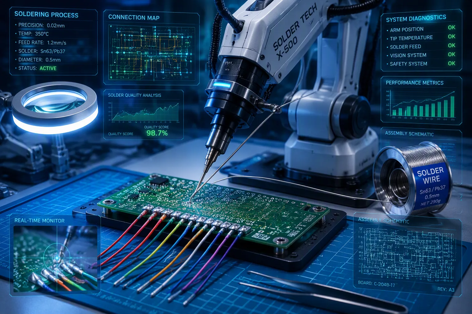
Automation now runs electronics manufacturing. Wire-to-PCB connections decide how reliable a product is. You need exact control over every soldering step. Which process needs matter most? How do you fix common problems?
This guide answers those questions directly. You will learn about equipment choices, key settings like temperature and dwell time, and how to design joints. You will also find out how to stop defects like spattering and heat damage.
Robotic Soldering gives you repeat results that manual work cannot match. Knowing the process well helps you use proven best practices. Use these tips to boost your own production quality and stay ahead.
Key Takeaways
Pick SCARA robots for fast, exact soldering. They manage tricky designs better than Cartesian robots.
Set the tip temperature between 345°C and 375°C for SAC305 solder, and keep dwell time under 8 seconds to avoid defects.
Pick the right solder and flux for your job. Water-soluble flux wets metal best, but you must clean it fully after.
Avoid spattering by controlling flux amount, preheating well, and using good flux-cored wire.
Use preheating and controlled cooling to lower thermal stress and create strong, dependable solder joints.
Robotic Soldering Equipment Essentials
Robot Types and Motion Control
The robot you pick changes how well soldering works. Two main types are used most often: SCARA and Cartesian robots. Each one fits different production needs.
SCARA robots are great for fast, exact soldering. Their arm design allows quick, steady moves on the X-Y axis. They can go faster than 1 meter per second and stay within ±0.01 mm of the target. A standard four-axis SCARA robot can reach 1,000 mm and carry about 10 kg. These features make SCARA robots perfect for high-volume work where accuracy matters every time.
Cartesian robots move in straight lines along three axes. They work well for big work areas and precise path control. They are very rigid and stable, which helps with heavy-duty soldering jobs. But to match SCARA accuracy, you need extra parts like ball-screw actuators and precision machined ball-rail tables.
For complex PCB layouts, SCARA robots have clear benefits. They take up less floor space but offer more movement options. Their built-in accuracy beats Cartesian robots without needing extra hardware. This is key when you deal with crowded parts and tight soldering spots.
Specification | SCARA Robot | Cartesian/Gantry Robot |
|---|---|---|
Movement | X-Y plane with vertical Z-axis | Three linear axes (X, Y, Z) |
Speed | High-speed, ideal for point-to-point | Generally slower for small workspaces |
Workspace | Broad shoulder-level envelope, compact | Very large work areas |
Payload | Handles heavier payloads than Delta robots | Excellent for heavy payloads |
Suitability | High-speed, precise horizontal movement | Large work areas and high rigidity |
SCARA robots are widely used for PCB assembly, SMD placement, soldering, and inspection. Cartesian robots need more space, move slower, and are less flexible because their movements are pre-set.
Solder Feeders and Tip Selection
Your solder feeder controls how material gets to the joint. Wire feeders push solder wire through a nozzle to the heated tip. Paste dispensers put down exact amounts of solder paste before heating. Wire feeders work best for most wire-to-PCB jobs because they allow steady, controlled feeding during the whole soldering cycle.
Tip shape directly affects heat transfer and joint quality. A well-shaped tip sends heat right to the connection point. You need a tip that fits your joint size and access needs. Bigger tips hold more heat but can damage small pads. Smaller tips give precision but need careful temperature control.
Pick your tip based on the wire size and pad dimensions you use. The right match helps solder flow smoothly onto copper surfaces. Robotic Soldering needs this level of care for steady results. Match your feeder speed to your tip temperature for the best wetting behavior.
Critical Process Parameters
Robotic Soldering needs careful tuning of wire size, flux type, flux amount, tip heat, and how long the tip stays on the joint. Each one changes how solder flows and how strong the joint is. You must control all of them to get the same good result every time.
Temperature and Dwell Time Control
Tip heat controls how fast solder melts and sticks to surfaces. For SAC305 lead-free solder, set your tip between 345°C and 375°C. This range is above the alloy's liquidus temperature of 221°C. It helps the solder bond well to wire and board connections. The exact tip heat you need depends on wire thickness and pad size.
Dwell time controls how long the joint stays hot. This time directly affects intermetallic compound (IMC) formation. The IMC layer connects the solder to the copper surfaces. If the layer is too thin, the joint is weak. If it is too thick, the joint becomes brittle and can crack. A short dwell time can cause poor wetting, while a long dwell time leads to de-wetting and oxidation.
Dwell Time Condition | Effect on IMC Layer |
|---|---|
Too much dwell time or too much heat | Brittle growth at the connection point |
Not enough heat input | Stops proper bonding between layers |
You must balance time and heat. A preprogrammed 8-second timeout, based on IPC Standard J-STD-001, helps stop PCB damage or pad lift-off. This limit gives you enough time to build a strong IMC layer without overheating the joint.
Proper IMC formation is needed to connect the solder and the board surface. If the IMC is too thin, the joint is weak. If it is too thick, the joint becomes brittle and cracks.
Solder Alloy and Flux Selection
Your choice of solder alloy and flux controls how well the solder wets and flows. Two common alloys are Sn63/Pb37 and SAC305. The table below shows their melting behavior.
Alloy | Solidus | Liquidus | Pasty Range |
|---|---|---|---|
Sn63/Pb37 | 183°C (361°F) | 183°C (361°F) | 0°C (0°F) |
SAC305 | 217°C (423°F) | 221°C (430°F) | 4°C (7°F) |
Sn63/Pb37 is a eutectic alloy. It melts at one single point and has no pasty range. This gives a fast, steady change from solid to liquid. SAC305 is non-eutectic. It has a 4°C pasty range where solid and liquid phases exist together. You must avoid moving the joint during this range to stop disturbed joints.
Flux removes oxide films and helps the solder wet the surfaces. The flux type changes wetting performance and cleaning needs.
Flux Type | Wetting Performance | Residue Nature | Cleaning Requirement |
|---|---|---|---|
Rosin (R, RMA, RA) | Good wetting; strong joints. | Sticky, can pull in dust/moisture; possibly corrosive. | Not always needed, but suggested for high-reliability or humid places. Clean with IPA or solvent. |
Water-soluble | Great wetting; strong oxide removal. | Very corrosive and conductive if left behind. | Must clean with deionized water right after soldering. |
Water-soluble flux gives the best wetting performance, but you must clean the residue fully. Rosin flux is more forgiving, but you may still need to clean it for high-reliability uses.
Alloy additions change wetting, strength, and oxidation. In Sn-Pb solder, a small silver addition can improve wetting. Flux-core wire carries flux inside the metal wire. As the alloy melts, the flux removes oxide films, lowers surface tension, and helps the solder wet.
Connection Types and Joint Design
Solder always moves toward heat and sticks to copper surfaces. This fact guides how you design every wire-to-PCB connection. You must plan your joint shape around this rule. A good design lets solder flow naturally into the joint. A bad design makes solder fight against gravity and surface tension.
Lap-Solder vs. Through-Hole Connections
Lap-solder connections work well for simple designs. You place a bare wire directly over a header pin. Then you apply solder to the overlap area. This method works for basic harnesses and prototype boards. The smallest pin spacing you should use is 2.45mm (0.100"). Tighter spacing makes soldering too hard to do reliably.
Follow these steps for a reliable lap-solder joint:
Clean surfaces on both the header pin and the cable wire.
Remove insulation to show the bare wire.
Place the wire so it overlaps the header pin.
Add solder to the overlapping part.
Cover the joint with heat shrink tubing to protect it from stress.
Through-hole connections give stronger mechanical bonds. You put the wire through a plated hole in the PCB. Then solder fills the hole from both sides. This method handles vibration and mechanical stress better than lap-solder joints.
Through-hole soldering needs careful control. Preheat the board to even out temperature across the whole assembly. This helps flux boil off and solder wet without damaging parts. Pick fluxes made for wave soldering that can go deep into holes. Set conveyor speed to give 3–5 seconds of wave contact. This lets capillary action fill the hole. Keep solder pot temperature steady to balance thickness and waste. Control wave height so it does not bridge across pads. Make sure boards are clean and leads are ready. Cut leads to 1.5–2 times the hole diameter for best flow. Use nitrogen to reduce oxidation and improve wetting on lead-free boards.
Wire Preparation and PCB Pad Layout
Wire preparation decides how well solder wicks into the strands. Pre-tinning the bare wire helps a lot. You feed solder into the hot wire, not onto the iron tip. This lets the alloy flow into the copper strands naturally.
Wire Gauge | Recommended Strip Length | Tinning Procedure |
|---|---|---|
AWG16 | 3–4 mm | Pre-tin the bare wire by feeding solder into it, letting it wick into the copper. Keep solder only on the exposed part. |
AWG18 | 4–5 mm | Apply flux, feed solder into the hot wire, and make sure it flows into the strands. Work fast to avoid melting the insulation. |
Match your strip length to your pad shape. For SMD pads, strip wire to about the same length as the pad. For through-hole pads, strip to about 5 mm. Always pre-tin both the wire and the pad. Use flux and make sure solder flows into the wire during reflow. This prevents cold joints and poor wetting.
Common Defects and Issues
Two common defects cause most rework in wire-to-PCB soldering: spattering and inconsistent wetting. Each one has clear causes and proven fixes.
Spattering and Solder Bridging
Spattering happens when flux boils too fast or when moisture contaminates the material. You see small solder balls scattered around the joint. These balls can cause short circuits later. The root cause is almost always flux-related.
Solder balls are caused by spattering, which is a result of flux-related issues. To avoid these defects, optimize flux volume, ensure proper preheating, and select the right flux type for the application. Specifically, excessive flux spread can be reduced by using flux with higher surface tension and lower preheat temperatures, and by using satellite-free drop-jet nozzles for precise application.
You can take several steps to stop spattering:
Flux Composition: Choose the right flux. This promotes smoother solder flow and helps keep splattering in check.
Premium Flux-Cored Wire: Use high-standard flux-cored wire. This ensures even flux distribution and fewer impurities.
Temperature Control: Set your soldering temperature correctly for the specific solder alloy.
Soldering Speed: Find the right speed. This prevents overheating while ensuring proper wetting.
Controlled Atmosphere: Use a controlled atmosphere like nitrogen. This reduces oxidation and spattering.
Workspace Cleanliness: Keep your workspace clean. This prevents contamination that can increase spattering.
Solder bridging connects two pads that should stay separate. This happens when you apply too much solder or when the tip stays too long on the joint. Proper tip selection and controlled feed rates prevent this issue.
Thermal Damage and Inconsistent Wetting
Thermal damage harms both components and the PCB substrate. Too much heat can lift pads from the board. It can also damage nearby parts. You must control your temperature profile carefully to avoid this.
Inconsistent wetting happens when the solder does not bond properly to the surfaces. The solder may bead up on the pad or lead. This indicates a lack of metallurgical bonding.
Flux activation follows a temperature-dependent sequence. Solvents evaporate at 150–180°C, concentrating the active ingredients. Then at 200–250°C, the activators attack and reduce surface oxides. Maximum activity occurs only within a narrow temperature window unique to each flux type. Deviating from this range leads to incomplete wetting.
Inadequate flux activation in Robotic Soldering stems from a thermal imbalance. Insufficient preheating leaves the flux chemistry unactivated, preventing oxide reduction. Excessive preheating evaporates the carrier too quickly, causing flux starvation. In both cases, the solder cannot wet the pad or lead. The corrective action is to maintain a delicate balance of time and temperature.
Here are the common wetting defects and their causes:
Defect | Visual Indicator | Flux-Related Root Cause | Corrective Action |
|---|---|---|---|
Cold joint | Dull, grainy appearance | Insufficient activation temperature | Verify profile, increase activity level |
Insufficient Wetting | Solder beads on pad or lead | Dirty/oxidized leads; wrong flux type; inadequate temperature profile | Clean surfaces; use active flux; verify reflow settings |
Dewetting is another problem. Solder pulls back from the copper surface. This occurs when improper flux activity or insufficient preheating hinders wetting. The corrective action is to select a flux with strong oxide-removal properties. Test its performance regularly. Replace it if degradation is detected.
Follow this checklist to correct inconsistent wetting:
Verify the flux manufacturer's recommended activation temperature profile.
Measure the top-side board temperature to ensure it does not exceed the flux's degradation point.
Check the drop-jet fluxer for clogs or inconsistent spray patterns that might leave areas unfluxed.
Ensure the time between flux application and wave contact does not exceed the flux's active lifespan.
Robotic Soldering Process Optimization
Preheating and Controlled Cooling
Warming up the PCB before soldering lowers the shock that heat can cause to parts. You heat the board to a set temperature before the soldering tip touches the joint. This stops sudden heat changes that can warp the board or stress its parts. Steady preheating keeps the PCB at a stable temperature, which helps the solder flow better.
For robotic through-hole soldering, warm the board to 100-150°C. This keeps the heat difference low when the tip meets the joint. For lead-free reflow work, you need higher preheat temperatures of 150-180°C because the final solder temperature is higher. A gentle ramp rate of 1-3°C per second limits stress on the board.
Good preheating does more than just reduce heat shock. It lets heavy parts like connectors soak up enough heat for proper solder wetting. This lowers the chance of cold joints while shielding heat-sensitive parts. Preheating also helps the flux work at its best. The solvents in the flux evaporate during preheating, creating a more stable and reliable soldering setup.
Cooling down slowly after soldering stops cracks from forming. You must let the joint cool at a steady pace. Fast cooling creates brittle intermetallic compounds. Slower cooling lets the solder harden evenly, making a stronger mechanical bond.
Quality Control and Monitoring
Watching the process as it happens ensures every joint meets your quality standards. You need systems that check conditions during the soldering cycle, not after it ends.
Temperature sensors placed near the soldering tip give you precise control. A sensor positioned 3mm from the tip enables accurate heat transfer and consistent joint quality. The Tip Position Corrector automatically fixes tip slippage caused by thermal expansion. The Uni-Tester measures tip temperature, tip-to-ground potential, and resistance according to IPC J-STD-001G standards.
Vision systems check placement and joint formation. Fiducial correction systems use board marks for pinpoint accuracy. AOI vision sensors with AI capabilities detect features, patterns, and edges in real-time. They verify solder joint formation as it happens.
Statistical process control tracks your process capability over time. You define quality characteristics like solder joint integrity and tip temperature. You collect baseline data to determine natural process variation. You select control charts like X-bar and R charts for continuous variables. You train operators to read and respond to these charts. You integrate with digital tools for real-time monitoring and alerts.
In electronics assembly, SPC ensures solder joint quality and component placement accuracy. It detects small shifts in process performance, such as changes in solder paste volume or reflow temperature. This prevents defects before they escalate.
Selecting the right robot, tuning temperature and dwell time, and designing joints for manufacturability form the foundation of successful wire-to-PCB soldering. Understanding defects like spattering and thermal damage helps you implement effective preventive measures before they cause costly rework.
The quantified benefits of robotic soldering are substantial:
Metric | Robotic Value |
|---|---|
Process Repeatability (Cpk) | 1.67–2.0 |
Defect Rate (DPMO) | 85 |
First-Pass Yield | 99.6% |
Throughput | 540 boards/shift |
Labor Cost Reduction | 50–70% |
Annual Rework Cost | <$8,000 |
These numbers show why automation pays off within 12–18 months. Apply these strategies to your own processes. You will achieve consistent joint quality, reduce costs, and remain competitive in automated manufacturing.
FAQ
What is the ideal tip temperature for lead-free soldering?
For SAC305 lead-free solder, set your tip between 345°C and 375°C. This range is above the alloy's 221°C melting point. It helps solder flow well without overheating the joint or harming nearby parts.
How do I prevent solder spattering?
Spattering happens when flux boils too fast or moisture gets into materials. Pick high-quality flux-cored wire, control your soldering speed, and keep your workspace clean. Using nitrogen also cuts down oxidation and spattering during soldering.
What causes cold joints in robotic soldering?
Cold joints occur when flux activation temperature is too low. The flux cannot clean oxides from the surfaces. Check that your temperature profile matches the flux maker's instructions. Raise the activity level or adjust preheating to get full wetting.
How long should the soldering tip stay on a joint?
Follow the IPC Standard J-STD-001 rule of an 8-second timeout. This limit stops PCB damage and pad lift-off. It also allows enough time for proper intermetallic compound formation without making brittle joints.
Can I use the same robot for different PCB designs?
Yes. SCARA robots handle complex layouts with high speed and accuracy. You can reprogram motion paths and adjust soldering settings for each new board design. Fiducial correction systems use board marks to keep pinpoint accuracy across different products.
See Also
A Practical Guide For Double Sided Reflow In Pcba Manufacturing
Key Process Standards For Reflow Soldering In Surface Mount Assembly
Essential Technical Guidelines For Wave Soldering In Smt Assembly
Why Nitrogen Reflow Matters For Automotive Smt And Pcba Products
Important Technical Requirements For Wave Soldering In Dip Assembly
