Press-Fit Connector Assembly Process
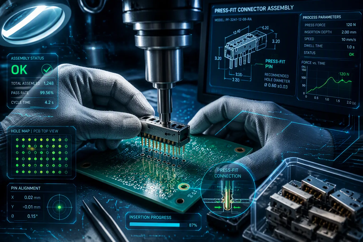
A press-fit connector joins wires to a pcb without solder. You press its pin into a plated hole. This assembly process is fast and highly repeatable. It also lowers production costs. You can complete connections in seconds.
This guide explains the complete process. You will learn how to prepare your materials. You will see the step-by-step method. Finally, you will discover how to check joint quality. You will also learn how to avoid common mistakes.
The technology is simple. You need the right tooling and a clean pcb. The press fit connector uses mechanical pressure. This pressure creates a tight, gas-proof joint. That joint resists vibration and corrosion.
Key Takeaways
Press-fit connectors make strong connections without solder by pressing parts together to create an airtight seal.
They provide more dependable performance and hold up better against shaking and temperature changes than soldered joints.
Good preparation means picking the right tools and making sure the holes in the PCB are the correct size.
Inserting the connector needs straight, steady pressure. After insertion, checking the joint and testing for continuity confirm it is good.
You can avoid common problems like bent pins and damaged plating by using the right materials and following the process steps carefully.
The Press-Fit Connector Process: An Overview
Defining the Solder-Free Connection
A press-fit connector makes an electrical joint without heat or solder. You push a metal pin into a plated hole on a circuit board. The pin is a little bigger than the hole. This size difference creates a tight fit. The board material squeezes around the pin as it goes in. That squeeze keeps steady pressure between the metal parts.
This pressure creates a seal that keeps air and moisture out. The connection does not rust or oxidize. You get this result using only mechanical force. The press-fit method works because materials bend a little. The pin gets slightly smaller. The hole plating stretches outward. Both parts want to go back to their original shape. That force keeps the connection tight.
The process needs accuracy. You must line up the pin straight into the board. You must push with steady force. Press-fit systems use pins that bend or pins that push material aside. Each type works for different uses. The result is the same: a reliable connection without solder.
Key Advantages Over Soldering
Press-fit connectors beat soldered joints in several clear ways. Reliability is the main benefit. Tests from IEC 1709 show press-fit connections are 10 times more reliable than soldered joints. They also fail much less often, up to 30 times better than soldering.
The mechanical hold gives better resistance to shaking. Solder joints get weak from constant vibration. Press-fit joints do not crack from heat changes. The connection does not break at the surface. Contact resistance stays below 10 mΩ even under load. Solder joints get higher resistance over time as metal layers grow.
The market shows these benefits. Industry reports say the press-fit connector market will grow from $8.5 billion in 2024 to $13.8 billion by 2034. Another study says the market is $10.01 billion in 2025 and will reach $16.46 billion by 2035. Both forecasts show steady growth near 5% each year.
Press-fit technology supports high-density board designs. You can place connections closer together without heat damage. The process avoids solder problems like bridges or gaps. You can also fix the connection. You can remove and replace a press-fit connector without harming the board. This is useful in tight designs where space is limited.
The table below shows key performance comparisons:
Metric | Press-Fit Value | Solder Baseline |
|---|---|---|
Reliability (IEC 1709) | 10× higher | 1× (baseline) |
Current-carrying capacity | 30–100 A per bus bar | Not specified |
Contact resistance under load | <10 mΩ (stable) | Increases over time |
Thermal cycling failure | Immune to crack propagation | Fatigue cracks at interface |
Vibration resistance | Superior mechanical lock | Solder fatigue |
Press-fit designs also make manufacturing easier. You skip the soldering step entirely. You save on energy costs. You remove flux and cleaning chemicals from the process. The connector pins have tight size limits. The finished hole diameter must stay within ±0.05 mm of what the maker recommends. This precision gives consistent joint quality on every board you make.
Preparing for Press Fit Connector Assembly
Selecting the Correct Insertion Tooling
The tooling you choose decides how good each joint will be. Manual presses work well for low-volume production or testing. These hand tools give you direct control over the insertion force. You can feel when the pin is in place. For medium volumes, pneumatic presses apply steady pressure with less operator effort. They reduce fatigue and keep the process consistent across long runs.
Automated machines handle high-volume production. These systems fit into your line and run all the time. Vibratory bowl feeders turn and push press-fit pins to the insertion head by themselves. Stick magazines do the same job for pins that come in tubes. Both ways remove the need for hand handling. This automation lowers the chance of bent pins and makes the whole process faster.
Your press-fit system needs tooling that matches your connector design. Different pin types need different insertion heads. Compliant pins need a ram that spreads force evenly across the contact. Solid pins need a faster increase in force. Check the connector maker's datasheet for the suggested insertion force range. Going beyond that range harms the pin or the pcb.
Ensuring PCB and Connector Readiness
A clean, undamaged pcb is needed for a reliable press-fit connection. The finished plated hole diameter must meet tight limits. The table below shows the key parameters you must check before starting.
Parameter | Tolerance / Requirement |
|---|---|
Finished plated hole diameter | ±0.003 to ±0.004 in (±0.076 to ±0.102 mm) |
Board thickness | ±10% (common for commercial constructions) |
Annular ring | Must accommodate manufacturing tolerance stack |
Press-fit specific requirement | Follow component manufacturer's recommended finished-hole requirements |
You must work with your PCB maker. The hole diameter and plating quality directly affect the mechanical and electrical connection. A hole that is too big gives a loose fit. A hole that is too small cracks the plating when you push the pin in.
Look over your connectors before you start. Visual inspection checks contact alignment, housing condition, and labels. Microscopic inspection shows fine-pitch contact problems, surface scratches, oxidation, and bent terminals. Dimensional inspection measures contact spacing and pin height. Functional testing checks continuity and contact resistance. These checks catch bad parts before they go into your assembly line.
Your assembly and press process controls should include these inspection steps. They stop costly rework and make sure joint quality is the same every time. Good preparation takes time, but it saves you from problems later in production.
Step-by-Step Guide for Press-Fit Connectors
Executing the Insertion and Seating
Start by lining up the connector at a right angle to the PCB surface. A 90° angle is very important. If you tilt it, the pins can bend or the hole can get damaged. Push straight down with steady, even force. Do not wiggle the tool or push at an angle. The press-fit connector goes into the hole with a certain amount of resistance. You know the pin is fully in place when the resistance suddenly drops.
For solid rectangular or square pins, you use Massive Press-fit Technology (MPFT). This method needs specific settings to work well. You must push with a force between 60 N and 250 N per pin. The speed of pushing should be between 100 mm per minute and 250 mm per minute. Push at a 90° angle to the board surface. After insertion, the holding force is 60% to 80% of the pushing force. You need a press-in pad with holes that are 0.3 mm larger than the product hole pattern. Do not chamfer these drill holes. Leave a gap of 0.1 mm to 0.5 mm between the board and the socket. After pressing, the pins must stick out more than 0.2 mm from the board. This makes sure they touch the copper sleeve fully. Both the Powerelement and the PCB must be at room temperature before you start. Keep other parts at least 4 mm away from the Powerelement. A simple toggle press works for making prototypes. No special equipment is needed.
IPC-A-610 visual inspection requires checking that SMT parts sit flat with no extra space under them. For through-hole (THT) parts, the leads must stick out evenly through the holes without bending or spreading. You must check tilted parts that might move during soldering. Use side lighting to find tiny gaps under the parts.
Post-Insertion Inspection and Verification
After you put the pin in, you must check every press-fit pin connection. Look at the connection to see if it is seated correctly. Signs of a good connection: the terminal is fully in place at the right height and position. It is not tilted or turned. The space between nearby terminals is correct. The wire seal position matches the terminal depth.
Watch for these defects that indicate a poor connection:
Terminal too high or too low
Terminal tilted or at an angle
Missing terminal or wrong type of terminal
Terminal pushed out or turned
Wrong cavity or missing seal
Two pins inserted in the same hole (double insertion)
For fish-eyed press-fit pins, you need to press the component with 5 kg of force spread evenly. Use special tooling that keeps the component exactly parallel to the board. This straight insertion makes sure the pin enters the hole cleanly and does not cause cracks.
You do a continuity test with a digital multimeter. Follow these steps:
Set your DMM to resistance mode (ohms).
Touch one probe to the pin on the top side of the PCB.
Touch the other probe to the matching pad or trace on the bottom side.
Read the resistance value. A good press-fit pin connection shows a reading close to zero ohms, usually below 10 mΩ.
Repeat this test for every pin in the connector.
If you get an open circuit or a high resistance reading, the pin is not fully in or it is damaged. You must take out and replace that connector. This test finds problems early. It stops failures when the product is used. You should write down all readings for quality records. The press-fit process gives steady results when you follow these steps. Each connection you check becomes a dependable part of the final product.
Ensuring Press Fit Connector Reliability
Common Defects and How to Avoid Them
Press-fit assembly works very well, but problems can still happen. You need to know the three most common failure types. Bent pins occur when a pin misses its hole, touches the hole edge, or hits the lower fixture during insertion. Damaged hole plating happens when copper scrapes, cracks, or separates because the hole, pin, or process settings are out of spec. A connector not fully seated results from early stoppage due to a pin blocking, tooling getting in the way, the housing touching something, or wrong press force settings.
These defects directly hurt your pcb reliability. If the pin is not fully in, it loses its mechanical hold. This can cause the terminal to move or come out. The result is loss of electrical contact or random faults, especially in harsh conditions. A gap between the connector and the board larger than 0.10 mm means it is not fully seated. This creates poor insertion feel, grounding problems, mechanical instability, and lower long-term reliability. The highest stress happens just before full seating, and pushing too far can permanently damage compliant pins, the cage structure, and grounding features.
You can prevent these defects with careful process control. The mechanical squeeze creates a gas‑tight joint, which is key for long‑term reliability. Several factors decide if your press‑fit system makes this seal:
Material Selection: High‑strength copper alloys (CuSn, CuNiSi) give high yield strength, fatigue resistance, and little stress relaxation to keep spring force over time.
Plating: Tin plating is important because it is soft and helps cold welding, forming a gas‑tight interface. Nickel is bad because it is hard, raises insertion force, and speeds up stress relaxation.
Geometry: Compliant zone designs (eye‑of‑the‑needle, fish‑eye) give controlled elastic deformation and even stress distribution, which is needed for long‑term contact stability.
Deformation Type: The pin must work in the elastic deformation zone. Plastic deformation is a failure mode that leads to permanent loss of spring force and higher contact resistance.
Hole shape and plating quality also matter. A bad plated‑through‑hole shape (hourglass) or uneven plating cuts down contact area and retention force. A hole that is too large or too small compared to the pin's compliance causes either too much insertion force or not enough retention. Dirt, poor cleanliness, or misalignment during insertion leads to joints that are not gas‑tight. Never solder or tin the compliant section. Soldering ruins its elasticity and creates brittle interfaces, harming the mechanical deformation needed for a reliable connection.
Testing Methods for Joint Integrity
You must check each press‑fit connector joint after assembly. Testing confirms that your process makes reliable connections. Several standard methods test mechanical integrity.
Certified press fittings are checked through pressure, tensile/pull‑out, and cyclic or vibration performance tests, as recorded by certification standards like DVGW, WRAS, and ASME. These standards confirm that the mechanical integrity of press‑fit joints is carefully tested for safety and reliability in critical uses.
You can use these testing ideas in your own quality program:
Pull‑out force testing: Measures the force needed to pull the pin out of the hole. It directly checks the mechanical integrity of the press‑fit joint under pulling load.
Burst pressure testing: Hydraulic pressure tests push the fitting to its bursting point. This checks the joint's ability to handle extreme internal pressure.
Vibration resistance testing: Seismic and vibration tests copy worst‑case situations. This confirms the joint's mechanical stability under moving loads.
For production checks, you already learned the continuity test with a digital multimeter. Use this electrical check together with visual inspection for full assurance. This mix of testing methods makes sure your press‑fit pins keep their gas‑tight seal over time. The result is a press‑fit connector that gives steady performance in high‑density pcb designs. Your attention to these details directly improves system reliability. When you follow these steps, you get the durability needed for high‑reliability uses. The press‑fit process rewards careful work with connections that beat soldered joints in tough environments.
The press-fit connector assembly process gives you a precise, reliable alternative to soldering. You prepare the pcb and tooling carefully. You insert the connector with straight, controlled force. You inspect every joint after pressing. Industry experts recommend a three-stage quality system. Use a non-contact system to check pin alignment before pressing. Verify pin position and coplanarity after pressing. Use a lens system to inspect pin integrity. Compliant pin designs, like the press fit connector from TE, reduce stress on pcb holes. These pins create a reliable connection that lasts. The method offers higher density connections and easy repairability.
Check manufacturer datasheets for specific details on your components.
FAQ
What tooling do I need for press-fit assembly?
You need a press that fits how many parts you make. Manual presses work for prototypes. Pneumatic presses suit medium runs. Automated machines handle high volumes. Your tooling must match your connector design. Check the manufacturer's datasheet for the recommended insertion force range.
How do I fix a bent pin during assembly?
Stop the press right away. Remove the connector carefully. Inspect the pin under magnification. If the pin shows damage, discard the connector. Do not try to straighten it. A bent pin forced into the hole will damage the plated through-hole and ruin the pcb.
How does press-fit reliability compare to soldering?
Press-fit connections show 10 times higher reliability than soldered joints in IEC 1709 tests. They resist vibration better and do not crack from thermal cycling. The gas-tight seal prevents corrosion. Contact resistance stays below 10 mΩ under load. This reliability makes press-fit ideal for demanding applications.
What testing methods verify joint quality?
You perform continuity testing with a digital multimeter. Set the meter to resistance mode. Touch probes to opposite sides of the board. A good joint reads below 10 mΩ. You also inspect visually for proper seating. Pull-out force testing measures mechanical strength when needed.
Can I remove and replace a press-fit connector?
Yes, you can remove press-fit connectors without damaging the board. This repairability sets them apart from soldered joints. Use the correct extraction tool to pull the connector straight out. Inspect the hole before inserting a replacement. The new connector will form a fresh gas-tight seal.
See Also
Standard Surface Mount Assembly Techniques And Process Sequences
Best Practices For Assembling Flexible Circuit Boards For Peak Efficiency
Understanding Surface Mount And Through-Hole Assembly For Circuit Board Production
Achieving Precision In Dual Inline Package Assembly And Hole Alignment
Effective Strategies To Optimize Hardware Assembly For Improved Outcomes
