Electric Vehicle Powertrain PCBA Manufacturing
You create modern power electronics. Fast EV growth increases the demand for automotive PCB parts in electric cars. As technical buyers, you make powertrain PCB modules, such as traction inverters, BMS, chargers, and converters.
Heavy heat stress means you need strong automotive PCBA designs. Just like ADAS, these PCBA units must pass high-voltage tests. Both ADAS and powertrain PCB modules need to have excellent quality. You follow IATF 16949 and ISO 26262 safety rules during PCBA Manufacturing and production. Advanced car electronics require good heat control for every PCBA unit. Your electric powertrain depends on reliable automotive PCBA layouts. A skilled automotive PCBA team helps build your PCBA. Proven automotive PCBA methods improve your powertrain PCB systems. Careful automotive PCBA assembly work protects your final PCBA.
Key Takeaways
EV powertrain PCBAs must strictly follow the IATF 16949 and ISO 26262 safety rules.
Silicon carbide MOSFETs and thick copper layers move extreme heat away from high-voltage electrical circuits.
Galvanic isolation barriers keep safe low-voltage microcontrollers protected from dangerous high-voltage battery lines.
IPC-2221 standards enforce minimum trace spacing rules to prevent surface sparks in high-voltage designs.
Vacuum reflow soldering drops solder void rates below 1 percent for better heat flow.
Press-fit connectors replace normal soldered joints so they can handle strong vehicle shaking without breaking.
Protective coatings and liquid resins cover heavy-duty circuit board parts to defend them against water and hard drops.
3D AXI X-ray inspections find hidden solder defects under thick copper layers to follow IPC Class 3 rules.
Key Subsystems in Automotive PCBA
You rely on connected parts to run an electric car smoothly. Your power control system brings together the main controller, battery unit, and motor drive for best results. Unlike basic advanced driver assistance systems, these adas power modules must handle extreme heat changes. You choose AEC-Q200 qualified passive components to guarantee strong dependability in all car electronics. Every powertrain systems pcb in this design powers vital driving tasks next to regular adas safety modules.
Traction Inverter Power Stage
Silicon Carbide Integration
You turn direct current from the battery into alternating current for the motor with smart power switches. Modern silicon carbide MOSFETs help your automotive pcba switch power much faster. Your powertrain systems pcb layout uses insulated metal substrates to pull heat off power parts fast.
You deliver maximum electrical power while keeping nearby low-voltage pcba circuits completely safe. Picking strong parts keeps signals clear during tough temperature changes inside your ev module.
Gate Driver Board Layout
Your gate driver board manages heavy power switches with great accuracy. You place thick copper multilayer boards inside your automotive pcb assembly to carry large currents safely.
You separate high-voltage power paths from control logic to protect the system. Your adas sensors and powertrain systems pcb modules follow strict noise rules under CISPR 25 standards.
High-Voltage Battery Management Systems
Cell Monitoring Circuitry
You check battery cells using exact testing circuits built on your automotive pcba. The monitoring board reads cell voltages from 0 V to 5 V with tiny errors under 2.2 mV using 16-bit converters on your powertrain systems pcb.
You use AEC-Q100 certified chips to handle connected battery cells inside high-voltage modules. This clever automotive pcba design stops overheating and helps your battery last longer.
Galvanic Isolation Architecture
You shield low-voltage microcontrollers from high-voltage battery wires with strong galvanic isolation barriers. A simple two-wire isoSPI interface changes full-duplex SPI data into differential signals up to 1 Mbps.
Tiny transformers block high direct-current voltages while sending signals across magnetic fields safely. You add common-mode chokes on the powertrain systems pcb to stop noise during 200 mA bulk current injection testing.
On-Board Chargers and DC-DC Converters
High-Frequency Transformers
You change power from the grid to fill high-voltage battery packs using an on-board charger. High-frequency transformers adjust electric voltage levels across isolated safety zones inside small automotive pcba units.
Your powertrain systems pcb holds special magnetic parts that handle high switching power levels like 6.6 kW. Good board design on your automotive pcba keeps heat low near active power transformers.
Bi-Directional Power Flow
You allow two-way power movement between the main battery pack and outside electronic loads. Dual active bridge setups help your automotive pcba turn direct current back into alternating current for extra equipment.
You combine extra DC-DC converters on the same powertrain systems pcb to run standard 12 V car electronics. This single automotive pcba setup cuts down total weight and boosts overall ev energy efficiency.
DFM for Powertrain Systems PCB Design
Heavy Copper Stackups and Substrates
Multi-Layer Heavy Copper
To handle large electric currents in your pcba units, you build thick copper layers inside the board. Increasing the weight of these copper planes up to 4 or 6 oz spreads heat sideways across the panel.
A 2 oz copper line gets rid of about 30% more heat than a 1 oz line of the same width. You balance the copper layers evenly to prevent the powertrain systems pcb from bending during manufacturing.
High-Tg FR-4 and Ceramics
You choose board materials designed to run constantly above 150°C with high Tg thermal ratings. Laminates made with over 50% resin and tight glass weaves stop inner electric leaks in your powertrain systems pcb.
You select low-expansion laminates around 14 to 17 ppm/°C that stretch at the same rate as silicon and copper. Picking materials with a Comparative Tracking Index of 600 or higher protects your high-voltage pcba from surface sparks.
Thermal Management Structures
Thermal Vias and Heatsinks
You place patterns of thermal vias and embedded copper pieces inside the board to lower heat resistance. This setup moves heat away from hot power parts directly into the inner layers of your powertrain systems pcb.
You spread out high-power parts across the board to prevent hot spots from forming in small areas. Putting temperature sensors near delicate circuits helps you track heat levels better across your pcba module.
Insulated Metal Substrates
You use insulated metal substrates to quickly move heat away from electronic components toward attached metal baseplates. Aluminum or copper bottom layers draw thermal energy out of your high-current pcba.
You check working temperatures and model heat flow early during your automotive pcba design phase. Using balanced layer patterns keeps the insulation safe across every powertrain systems pcb you make.
Creepage and Clearance Compliance
IPC-2221 Separation Standards
You follow IPC-2221 distance rules to stop surface sparks from jumping between high-voltage lines on your powertrain systems pcb. For power levels from 301 V to 500 V, you keep a minimum gap of 2.5 mm between traces.
Voltage range | IPC-2221 minimum clearance |
|---|---|
Up to 30 V | 0.1 mm |
31-150 V | 0.6 mm |
151-300 V | 1.25 mm |
301-500 V | 2.5 mm |
>500 V | 0.005 mm/V |
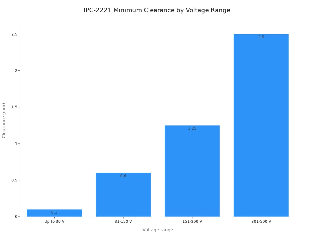
For systems over 500 V, you set the main gap starting at 0.25 mm for 500 V and add 0.0025 mm for every extra volt. High-voltage ev drive systems above 500 V use this formula to increase safety spacing evenly.
Anti-Tracking Board Trenching
You cut physical slots into the board to increase the surface path distance on your powertrain systems pcb. Putting isolation trenches between high-voltage lines stops electrical shorts inside your ev system.
You leave wide gaps around high-power switches on your electric module pcba to ensure safe operation. High-pot testing at 1500 V confirms that the insulation works correctly on your finished pcba system. You check every completed pcba and powertrain systems pcb to ensure full high-voltage safety.
Powertrain PCBA Manufacturing and SMT
Surface mount technology lets you place many parts close together on power board modules. Automating assembly allows you to shrink component sizes while speeding up modern pcba manufacturing. Because thick copper layers and heavy power components soak up heat rapidly, you must use special board handling methods during pcba manufacturing. Careful temperature monitoring protects vital board layers as parts move quickly through high-speed assembly lines.
Advanced SMT Assembly Processes
High-Density Component Placement
Building modern power controllers requires you to fit over 100 components into one square inch. Fast pick-and-place robots move with extreme precision to handle tiny 0201-sized parts. These machines hit exact positions within a tight tolerance of ±0.01 mm. Built-in vision systems scan part marks in real time to fix minor positioning shifts on every pcba board.
Placement Parameter | Operational Value |
|---|---|
Placement Speed | Over 100,000 parts per hour |
Placement Accuracy | ±0.01 mm positioning tolerance |
Minimum Component Size | 0201 surface-mount parts |
Maximum Component Density | Over 100 parts per square inch |
High-speed placement equipment places more than 100,000 components per hour. Advanced camera systems check part alignment before components touch the solder pads. This fast process helps you create tight powertrain systems pcb layouts without making mistakes on ev power modules. Camera systems check component leads to make sure parts sit cleanly across the pcba panel before reflow heating starts.
Solder Paste Stencil Design
You apply solder paste through accurate laser-cut stencils onto bare copper pads. Laser-cut stainless steel masks control paste volume with great accuracy. Thin stencil walls let paste release smoothly across tiny pad openings on a pcba surface. The amount of paste used directly controls the final joint strength on your automotive pcba.
Automated solder paste inspection tools measure paste height and pad coverage instantly. They check every packed pcba design to prevent solder bridges before mounting components. Thick copper layers change how heat moves inside each powertrain systems pcb layout. Using proper stencil openings deposits exact solder amounts to lock packed parts onto thick copper traces without spilling solder onto nearby pads.
Vacuum Reflow Soldering
Voiding Reduction Techniques
You run high-power electronics through a vacuum-assisted reflow oven to remove air bubbles. Standard thermal reflow traps gas bubbles inside liquid solder joints as they cool.
Conventional reflow creates solder void rates between 15% and 20%, but vacuum reflow drops total voiding below 1%.
Lowering air pressure while the solder is liquid pushes out hidden gas bubbles. Fewer voids improve electrical contact across every high-voltage pcba. Removing trapped gas pockets creates smooth heat paths under power parts. This step shields your power modules from heat failure when drawing heavy current.
Nitrogen Atmosphere Profiling
Thick copper planes up to 10 oz draw heat away from active joint areas. You choose high-Tg laminates rated above 170°C to withstand continuous exposure to high heat. High thermal mass creates a very narrow reflow profile window for your ev production line.
You pump inert nitrogen gas into heating zones to clear out oxygen during reflow. Nitrogen stops pad oxidation while heating heavy copper structures evenly across complex pcba layouts. Slow heating speeds guarantee reliable solder flow on your automotive pcba. Controlled heat profiles stop substrate warping across every complex powertrain systems pcb.
Selective Soldering and Press-Fit
High-Current Pin Soldering
You solder heavy power pins and large connectors using automated selective soldering tools. Mixed-technology boards put fine-pitch logic and thick power leads together on one automotive pcba. Selective soldering nozzles apply target heat to through-hole joints without overheating nearby surface mount parts.
You change solder pot temperatures to match the high thermal mass of heavy copper lines when designing your powertrain systems pcb. Controlled heat delivery prevents cold solder joints on your powertrain systems pcb. Steady flux monitoring ensures deep solder wetting through every plated board hole while guarding each automotive pcba against stress. Precise nozzle control keeps solder away from delicate nearby component leads on every pcba module.
Automotive Press-Fit Connectors
You push high-current press-fit pins straight into plated board holes to avoid solder flaws. Solderless press-fit joints withstand extreme mechanical shaking and quick heat shifts while driving the car. You press solid copper pins into copper holes using precise mechanical force controls.
This strong mechanical joint shields important automotive electronics from shaking damage over long driving cycles. You remove heat stress on nearby delicate logic chips inside your automotive pcba module when inserting connections. Strong press-fit joints improve your total automotive pcb assembly. Standard automotive pcb manufacturing relies on press-fit interfaces for high-current power input points. Your complete automotive pcba units meet tough automotive reliability rules for every automotive pcba design. Careful execution during assembly shields every powertrain systems pcb across the entire automotive pcba line.
High-Voltage Protection and Coating
Selective Conformal Coating
Acrylic and Silicone Materials
You pick suitable layer materials to protect your electric power units from sudden electrical sparks. Protective conformal coatings safeguard high-voltage pcba components effectively.
Conformal coatings can be used in high-voltage and power electronic applications because they improve dielectric strength and help prevent current leakage and electrical arcing.
Acrylic provides low costs and simple fixes for normal pcba assemblies. Flexible silicone stays stable between −50°C and 200°C. You spray silicone about 25–50 µm thick on delicate powertrain systems pcb zones during automotive pcba manufacturing.
Material | Dielectric strength | Thermal resistance | Chemical/solvent resistance | Flexibility | Reworkability | Best-fit context |
|---|---|---|---|---|---|---|
Acrylic | ~1000 V/mil | Up to 120°C | Limited | Good | Easy | Consumer/indoor/low-cost |
Silicone | ~500–800 V/mil | −50°C to 200°C | Moderate for moisture | High | Difficult | Outdoor, wide temperature swings |
Polyurethane | ~900–1200 V/mil | Up to 130°C | Superior for chemicals | Limited | Challenging | Harsh-chemical environments |
Automated Dip and Spray
Robotic spray systems put helpful protective material over every single automotive pcba board. You control automated nozzles to cover target areas without dropping resin onto connector pins.
Set fluid application paths defend active powertrain systems pcb tracks across your pcba design. This mechanical process guards every automotive pcba unit against fluid mist during tough drive cycles.
Encapsulation and Potting
Thermally Conductive Resins
Heavy potting mixes seal entire board modules from hard physical drops and moisture. You pack high-voltage cases with Araldite CW 30388 / Aradur HW 30389 epoxy resin to reach heat conduction of 0.95 W/(m·K) and a Tg of 200°C.
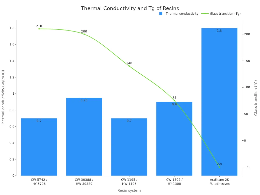
Arathane 2K polyurethane adhesive supplies 1.8 W/(m·K) heat conduction and remains soft down to -50°C. Adding this strong material keeps heat low while protecting your high-power pcba layout inside power modules.
Vacuum Dispensing Systems
You run vacuum casting tools to spread liquid potting resin around tight pcba components. Controlled vacuum suction draws trapped air pockets out of tight spaces inside your automotive pcba enclosure.
Clearing trapped air eliminates open spaces within the filled outer case. This smart casting step strengthens your high-power powertrain systems pcb against rough road shakes.
Environmental Reliability
Moisture Resistance
You check completed pcba units against high moisture limits under strict ISO 16750 rules. Sealed board coatings stop stray water drops on the pcba surface from starting short circuits across high-voltage traces on your automotive pcba module.
Parylene C coatings offer micro-thin insulating layers measuring between 10–20 µm. Spraying parylene shields your powertrain systems pcb while saving necessary open space across your automotive pcba assembly.
Dendrite Growth Mitigation
Strong electrical energy between copper paths speeds up tiny metal dendrite growth over time. You add safety coatings over every automotive pcba build unit to stop conductive crystal lines from spreading across the pcba shield.
Spotless build rooms lower tiny dirt particles on every pcba panel right before applying outer coatings. Careful factory work defends your powertrain systems pcb against energy leaks across long car lifespans in automotive pcba design to keep power performance steady.
Quality Control and Testing Protocols
You must ensure top board reliability for electric vehicle power drives. Strict inspection steps prevent unexpected failures and keep drivers safe. Combining advanced optical tools with automated electrical screens brings high quality to every automotive pcba on your assembly line.
Automated Optical and X-Ray Inspection
3D AOI Defect Detection
You scan every pcba right after reflow soldering is complete. High-resolution cameras take clear photos of the board from several angles. Modern 3D optical tools quickly check part heights, component alignment, and solder shapes.
These automated systems spot lifted leads, missing parts, and tilted chips early. You catch assembly mistakes before boards reach final testing stations. Early screening stops bad parts from getting into delicate adas control boards.
3D AXI Void Analysis
Thick copper layers block visible light under large power modules. You use 3D X-ray machines to look directly through heavy copper board layers on your automotive pcba.
X-ray checks measure hidden solder gaps underneath power transistors. Reducing these gaps stops dangerous hot spots from forming while driving. You check joint quality to meet IPC Class 3 standards for all automotive pcba assemblies.
Electrical and High-Voltage Testing
In-Circuit Bed-of-Nails Testing
You run complete bed-of-nails tests to check component values on your automotive pcba. Special fixtures measure electrical resistance on main power paths down below 10 mΩ.
Repeatable test rules check signal speeds in CAN bus communication lines at 1 Mbps or higher to keep the system working together.
Heavy probes carry 10A per pin in parallel setups. You check power paths carrying 50A to over 300A without harming the pads. This process checks voltage stability while protecting connected adas sensors and logic chips.
Hi-Pot Safety Verification
High-voltage circuits need strong insulation barriers to stay safe. You perform high-voltage electrical tests to find insulation leaks on your automotive pcba build.
Apply over 1000V across high-voltage paths to check electrical insulation.
Check that ground insulation resistance reaches at least 1 MΩ on 800V+ systems.
Stop short circuits and electrical shocks before installing the boards.
This test routine keeps modern high-voltage car electronics safe during use.
Environmental Stress Screening
Thermal Shock Cycling
Extreme temperatures strain solder joints and board layers. You put each unit inside stress testing chambers.
These special chambers change temperatures quickly from -40°C up to 125°C. Rapid temperature shifts reveal hidden layer gaps and cracked metal traces. Heat cycling builds long-term quality for electric car controllers and nearby adas hardware.
HALT and Vibration Testing
You test every automotive pcba design with severe shaking. High-stress vibration tables act like rough road bumps over thousands of driving miles.
Automated tools monitor circuit connections during this physical stress test. This test phase proves that your finished automotive pcba units are physically strong. Strict factory controls keep quality high across all automotive pcba production batches.
Automotive Compliance and Standards
Quality Management Certifications
IATF 16949 Audit Compliance
You must satisfy strict global rules for your EV assembly lines. General ISO 9001 creates a basic quality management setup for daily factory operations. Still, car manufacturing requires complete IATF 16949 compliance. Regular audits mandate core tools to stop mistakes across every single work shift.
Automotive-grade PCBs must comply with strict specifications on thermal cycling, vibration, humidity, and long-term reliability, verified through extensive test regimes and audits. Achieving and maintaining IATF 16949 and meeting OEM-specific qualification processes are resource-intensive, which can limit new entrants and slow innovation when validation capacity is stretched.
ISO 26262 ASIL Integration
You run hazard analysis and risk reviews following ISO 26262 safety rules. This framework ranks potential dangers from ASIL A down to ASIL D. High-voltage power modules and advanced adas safety systems need very strict risk controls. Choosing AEC-Q100 qualified components boosts functional reliability across every single board.
ISO 26262 area | Extracted evidence supporting the query |
|---|---|
ASIL levels | ISO 26262 categorizes hazards from ASIL A to ASIL D to determine necessary safety measures. |
Verification and validation | Compliance requires extensive testing such as FMEA and hardware-in-the-loop testing. |
You balance high-power control logic and delicate adas circuit lines on one board. Good electromagnetic interference shielding protects vital signals from noise.
Production Part Approval Process
Level 3 PPAP Documentation
You send full Level 3 PPAP packages before starting mass production. This paperwork package shows your manufacturing skills to car buyers clearly. You supply first sample check reports together with exact size measurement records.
You check that automated factory lines deliver steady output across complete manufacturing runs. Thorough documentation protects every pcba lot from unexpected design changes.
Failure Mode Analysis
You run detailed failure mode and effects analysis during early design stages. Engineers study potential hardware problems to reduce real-world failures later. This workflow guides safety steps before placing components on your pcba build.
IATF 16949 audit area | Extracted evidence supporting the query |
|---|---|
VDA 6.3 process audit | Verifies process capability across development, pre-SOP, launch, and serial production. |
VDA 6.5 product audit | Verifies finished product conformity from customer viewpoint during serial production. |
VDA 6.3 audits check overall production capacity across your assembly floor. VDA 6.5 product audits confirm finished items match customer needs during main production.
Supplier Technical Evaluation
Component Traceability Systems
You track every part lot back to its first factory batch. Automated tools record scanner details while placing components on each pcba panel.
Compliance category | Standard / requirement | Relevance to automotive manufacturing |
|---|---|---|
Environmental management | ISO 14001 | Addresses waste, chemical handling, and energy monitoring during OEM onboarding. |
Occupational health & safety | ISO 45001 | Provides a safety framework for high-voltage testing and power electronics operations. |
Full tracking connects component batches, machine settings, and room conditions together. Complete digital records protect sensitive adas modules and main power parts. You keep exact history files for all electric vehicle module builds.
Wide Bandgap SMT Capabilities
You update placement lines to handle modern silicon carbide and gallium nitride chips. Wide bandgap power devices need special care during fast machine placement steps. You tune temperature profiles to shield fragile surface mount parts on complex pcba boards.
You test factory skills to maintain top automotive pcba quality levels through large production runs. Thorough technical checks confirm your supplier handles complex EV power builds. Skilled assembly crews build dependable automotive pcba modules for heavy driving uses. Every approved automotive pcba design operates smoothly inside modern vehicle platforms. You check every partner carefully to keep automotive pcba output steady for all delicate pcba units.
Dependable pcba manufacturing powers modern electric vehicles. You achieve success in ev projects by using smart DFM, high-density SMT, and great heat controls. Every automotive pcba easily handles tough heat. A strong powertrain systems pcb shields vital electric circuits. Testing checks full safety across your powertrain systems pcb. You preserve top quality throughout testing.
An IATF 16949 partner simplifies automotive pcb manufacturing. Vacuum reflow and 3D AXI protect every finished automotive pcba. Early planning boosts automotive pcb assembly yield on your powertrain systems pcb. Dedicated pcba manufacturing defends delicate ev modules. Advanced pcba processes guarantee long-lasting powertrain systems pcb reliability. Talk with an automotive pcba expert to upgrade your automotive pcba and craft your powertrain systems pcb alongside a trusted pcba team for full pcba success.
FAQ
Why do electric vehicle powertrain PCBAs require heavy copper layers?
Thick copper layers carry large electrical currents and move heat across your board. Adding copper up to 4 or 6 oz spreads thermal energy very well. This extra copper stops dangerous hot spots from forming. It keeps your power electronics running safely during heavy use.
How does vacuum reflow soldering reduce solder voiding in power boards?
Normal reflow traps gas inside melted solder, making 15% to 20% void rates. Vacuum reflow lowers air pressure while the solder is liquid to push out gas bubbles. This drops voiding below 1%, creating smooth heat paths under high-power transistors.
What clearance gap does IPC-2221 require for high-voltage powertrain designs?
IPC-2221 safety standards require set isolation spacing based on your operating voltage. For power levels from 301 V to 500 V, you need a minimum trace gap of 2.5 mm. Voltages over 500 V need even more space to stop surface sparks.
Why is automated 3D AXI essential for automotive PCBA quality control?
Thick copper layers and large power parts block light during basic visual checks. 3D AXI uses X-rays to look through heavy board layers easily. This tool measures hidden solder voids under parts to help your board meet strict IPC Class 3 car rules.
How do powertrain PCBAs interact with adas safety modules?
Main power controllers deliver steady electric energy to adas modules across connected car networks. Both setups follow strict CISPR 25 noise rules and ISO 26262 safety standards. Proper board grounding keeps high-voltage noise from messing up sensitive driver assistance sensors.
What quality certifications govern high-voltage EV PCBA manufacturing?
You must follow IATF 16949 rules for automotive quality management and ISO 26262 standards for safety. Factory lines need Level 3 PPAP approval before full production begins. These papers check part tracking, heat test strength, and steady work across every factory run.
Why do manufacturers use press-fit connectors instead of standard soldering for power pins?
Solderless press-fit pins slide tightly into plated copper holes with mechanical force. Press-fit joints remove solder flaws and easily handle strong driving shakes. This link method also shields nearby adas logic chips from high heat stress during board assembly.
See Also
Mastering Electronic Component Sourcing Strategies For Circuit Board Manufacturing
How Turnkey PCBA Solutions Manage Everything From Production Testing
Maximizing Operational Efficiency With Professional Contract Circuit Board Assembly
Understanding Printed Circuit Board Assembly Definition In Modern Electronics
Complete Electronics Manufacturing Guide From Bare Board To Testing
