PCBA for Imaging Systems: Ultrasound, MRI, CT
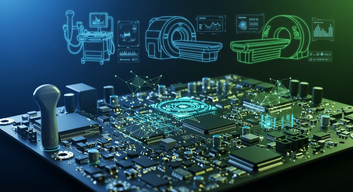
You rely on pcba to make important medical imaging systems work. High-reliability pcba helps medical devices like MRI, CT, and ultrasound perform well. Signal integrity and EMC are important for patient safety and clear tests. Medical standards guide every pcba design to keep you safe and help with point-of-care diagnostics. Good pcba design makes sure your imaging systems give correct results every time.
Key Takeaways
PCBA is very important for medical imaging systems like MRI, CT, and ultrasound. It helps these machines work safely and well.
Signal integrity and electromagnetic compatibility (EMC) are very important. They help make clear images and give good results in medical imaging.
Making PCBA strong and following medical rules keeps people safe. It also helps the machines work well in hospitals.
Reducing electrical noise by using good design helps make better images. It also keeps patients safer when using imaging systems.
New ideas in PCBA design, like making parts smaller and adding IoT, help medical imaging devices get smarter and work better.
PCBA in Imaging Systems
Core Functions in Medical Imaging
You need pcba to help imaging systems like MRI, CT, and ultrasound work well. These boards are very important for your medical devices. They do many jobs to keep your imaging equipment safe and working right. Here are some main things medical imaging pcbs do:
Power management: Switching regulators help ultrasound systems work better and stop interference.
Channel density: Boards with many channels fit in small spaces, which is good for small imaging devices.
Data handling: Processors on the board lower data rates, so you can see images in real time.
Size and thermal constraints: Smart design lets you put complex circuits in small spaces and keeps signals clear.
Reliability: Strong materials and careful design help your equipment last, even after cleaning or radiation.
These things help your imaging equipment do its main jobs. The table below shows how pcba helps in different medical devices:
Core Function | Application in Medical Imaging Equipment |
|---|---|
Signal processing hub | Signal acquisition and processing in CT, MRI |
Real-time data processing | Vital signs monitors (ECG, EEG) |
Precision control | Therapeutic devices (defibrillators, ventilators) |
Importance for Signal and Data Processing
You want clear images and fast results from your imaging systems. Pcba helps by supporting high-frequency signals and lowering noise. For example, in MRI machines, special pcba designs handle radio frequencies from 64 MHz to 400 MHz. This keeps signals strong and images sharp. In CT scanners, the boards process data very fast, which helps make good images.
Medical imaging needs very fast signal processing boards. These boards let your systems handle lots of data without losing quality. Good pcba design also stops electromagnetic interference, so your images stay clear. When you use advanced medical imaging pcbs, you get results you can trust and better care for patients.
Medical Imaging PCBA Requirements
Signal Integrity and EMC
You want your medical imaging systems to give clear results. To do this, you must focus on signal integrity and EMC in every pcba. High-frequency signals can get weak or mixed up if you do not control impedance or spacing. Problems like signal reflection and crosstalk can make your images look bad. Power integrity issues can also hurt image quality. You can use things like controlled impedance routing and differential signaling to keep signals clean. Solid ground planes help too. Decoupling capacitors and careful layout lower noise and voltage drops. These steps help your pcba meet tough rules for life-saving devices.
Reliability and Standards Compliance
You need your pcba to work every time, especially in important systems. Medical devices must be very reliable and follow strict rules. You should use IPC Class 3 guidelines and make boards in cleanrooms. Testing like functional testing and automated optical inspection checks for problems. Stress testing looks for long-term stability and electrical strength. You must follow rules like IEC 60601. This covers things like dielectric strength, creepage, and EMI control. The table below shows some main rules for quality and safety:
Requirement Type | Description |
|---|---|
Compliance | PCBs must meet Class 3 electronic requirements for medical devices. |
Record Keeping | PCB manufacturers must keep detailed records, including lot tracking. |
Qualification Standards | Installation, operation, and process qualification standards are needed. |
Certification | ISO 13485 compliant makers show quality and reliability certification. |
Minimizing Electrical Noise
You want to keep electrical noise very low in your pcba. Noise can cause mistakes in medical imaging and hurt patient safety. You can use design tricks like keeping analog and digital parts apart. Use low dielectric materials and put decoupling capacitors close to power pins. EMI shielding, ground planes, and careful signal routing also help stop interference. Simulation tools and good testing make sure your pcba meets fda and other rules. By doing these things, you make your medical imaging systems better and more reliable.
PCBA Design for Ultrasound, MRI, and CT
Ultrasound: Signal Processing and Miniaturization
Ultrasound imaging systems have special challenges. These devices need pcba that works with high-frequency signals. They must also keep noise low. If impedance is not controlled, images can get blurry. You need multilayer stackup designs to meet medical rules. Using IPC Class 3 fabrication helps your device last longer.
Making ultrasound pcba smaller is important. Flexible pcbs let you shape devices for easy use. This helps sonographers feel less tired. Small routing patterns lower signal loss and cross-talk. Lightweight designs make devices more reliable. The table below shows how these features help:
Feature | Description |
|---|---|
Transducer Performance | Better frequency, sensitivity, and bandwidth give clearer images and less noise. |
Miniaturization | More elements and good signals are key for wearables. |
Micromachined Ultrasound Transducers (MUTs) | These can be made in batches and are very thin for comfort and good use. |
Focusing on signal processing and miniaturization makes images clearer. It also makes systems work better. Good design and manufacturing help you meet strict medical pcba rules.
MRI: Magnetic Compatibility and Shielding
Magnetic compatibility is very important for MRI pcba. MRI machines have strong magnetic fields. These fields can cause eddy currents in the boards. EMI from digital parts and power supplies can hurt performance. You need multi-layer pcbs with special ground and power planes. These help keep fields inside and lower emissions.
Shielding protects sensitive pcba parts. You can use Faraday cages or shields made from aluminum or copper. EMI gaskets, vents, and shielded windows let air flow but block waves. Metal cans over noisy parts keep them away from analog bio-sensors. Ground vias connect shields to the ground plane for strong RF barriers. The table below lists important things to remember:
Key Consideration | Description |
|---|---|
Magnetic Field Effects | MRI machines make strong magnetic fields that can cause eddy currents in pcbs. |
EMI Sources | EMI comes from digital switching, power supplies, and high-current drivers. |
PCB Stackup Selection | Multi-layer boards with special ground and power planes help keep fields inside and lower emissions. |
Shielding Techniques | Shields are needed to block EMI, and MRI needs special designs. |
Grounding Strategies | Good grounding lowers voltage differences and common-mode currents for high-frequency use. |
Tip: Never use ferromagnetic materials in MRI pcba. Non-magnetic shields stop image problems and device heating.
Strong shielding and grounding make images better and systems safer. Good design and manufacturing help you meet medical rules.
CT: High Voltage and Thermal Management
CT imaging systems need pcba that can handle high voltage and heat. CT scanners process data very fast, sometimes over 1 GHz. You need materials that work well at these speeds. High power use makes a lot of heat, so you must cool it down.
Metal-core pcbs with aluminum or copper bases act as heat sinks. Heavy copper pcbs move heat away from hot parts. Special dielectric materials help cool high-power chips fast. This keeps the system working well for a long time. The table below shows ways to manage heat:
Thermal Management Technique | Description |
|---|---|
Metal-Core PCBs | Metal bases like aluminum or copper act as heat sinks. |
Heavy Copper PCBs | These boards move heat away from hot parts to stop overheating. |
High-Thermal-Conductivity Materials | Special materials cool high-power chips for steady use. |
Miniaturization is also important for CT scanners. Small designs must still work well. Using strong materials helps the device last through wear, moisture, and heat. Good design and careful checks help you meet medical rules and keep people safe.
Note: Good thermal management and high voltage handling keep CT imaging systems safe and images clear.
PCBA design affects every imaging system. Solving special problems for ultrasound, MRI, and CT makes images better and systems more reliable. Careful work and good sourcing help you make safe medical devices that meet tough standards.
Comparing Imaging System PCBAs & Future Trends
Differences and Similarities Across Modalities
Imaging systems like ultrasound, MRI, and CT have some things in common. All of them need to be very reliable and safe for patients. They use isolation barriers to keep patient circuits apart from other parts. Controlled impedance routing helps signals stay correct and stops mistakes. It is important to keep analog and digital parts away from each other to lower noise. Conformal coating keeps boards safe from water. Sterilization resilience means the devices can be cleaned many times and still work.
Here is a table that shows the main things these PCBA designs share:
Design Feature | Description |
|---|---|
High Reliability | Medical PCBs must work well in many situations to keep patients safe. |
Stringent Quality Control | Boards must be made with strict rules to stop problems. |
Isolation Barriers | These keep patient-contact circuits away from other parts. |
Controlled Impedance Routing | This helps signals stay clear and stops errors in imaging. |
Analog and Digital Separation | Keeping these apart lowers noise on important signals. |
This protects boards from water and dirt so they last longer. | |
Sterilization Resilience | Boards must handle cleaning many times without breaking. |
But each imaging system also has its own needs. MRI uses non-magnetic materials and special shields. CT needs good ways to handle heat and high voltage. Ultrasound needs small and bendable boards.
Innovations in Medical Imaging PCBAs
There are new trends changing how medical PCBA is made. Imaging devices now use less radiation, which is safer for people. Smaller devices can be used in emergency rooms and are easy to carry. New types of imaging like PET, SPECT, and MPI are possible because of better PCBA.
You can also see these new ideas:
MRI can use higher field strengths, so it needs new materials and better shields.
Low-field MRI makes scans cheaper and easier for more people.
MRI PCBs can now work with wearable and IoT devices for real-time checks.
More companies are trying to make PCBA in ways that help the planet.
Researchers have made wearable patches that use photoacoustic sensing to check blood flow and find tumors. These patches need special PCBs to fit all the sensors. In the future, more imaging systems will use IoT technology. This will let doctors collect data right away and help patients from far away. Flexible PCBs and 3D printing will make devices smaller and stronger. Artificial intelligence will help doctors look at data and find problems faster. Imaging systems will get smarter, safer, and more connected.
You need special circuit boards to make imaging systems work well and stay safe. These boards are made for each device to help them do better. Some studies show how these designs help:
Study Title | Key Findings |
|---|---|
Modular 7T high-impedance array for ex-vivo imaging | Makes parallel imaging work better. |
Optimization of 4-Port Asymmetric Elliptical Birdcage RF Coil for 1.5 Tesla MRI | Gives more even fields and better results. |
Combined volume T/R and surface Rx-only coils | Makes signals clearer for brain and spine tests. |
New ideas keep making devices safer and tests better. In the future, you will see smaller tools and smarter ways to look at data.
FAQ
What does PCBA mean in medical imaging?
PCBA stands for Printed Circuit Board Assembly. You use it to connect and control parts in imaging devices like MRI, CT, and ultrasound. It helps your machine work safely and gives clear images.
Why is signal integrity important for imaging systems?
Signal integrity keeps your images clear. If signals get weak or mixed up, you may see blurry or wrong results. Good PCBA design helps you avoid these problems.
How do you reduce electrical noise in PCBA?
You can keep analog and digital parts apart. You use shielding and ground planes. Decoupling capacitors also help. These steps lower noise and make your images better.
What standards must medical PCBA meet?
You must follow rules like IPC Class 3 and IEC 60601. These standards make sure your PCBA is safe and reliable. You also need ISO 13485 for quality.
Can you use the same PCBA for MRI, CT, and ultrasound?
No, you cannot. Each system needs special PCBA. MRI needs non-magnetic boards. CT needs boards that handle heat and high voltage. Ultrasound needs small and flexible boards.
See Also
Understanding PCBA Processing Needs for Medical Devices
Defining PCBA and Its Essential Components Explained
Exploring the Meaning of PCBA in Electronics
The Role of X-Ray Inspection in PCBA Quality Assurance
Sourcing Electronic Components for Effective PCBA Production
