Set Temperature vs. Actual Tip Temperature: Why Robotic Soldering Results Can Vary
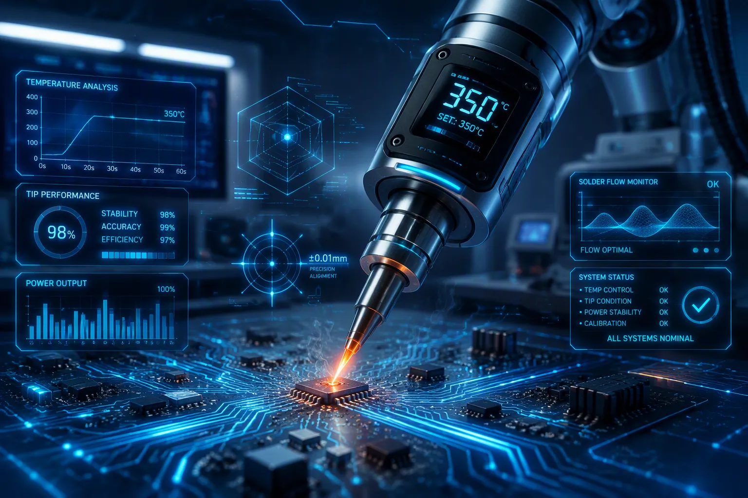
Imagine your soldering station displays 842°F, but the actual tip temperature is only 275°F. This gap between the set temperature and the real soldering temperature creates a major problem for robotic soldering. You rely on the display to control the process. However, the actual heat delivered to the solder joint is much lower. This directly impacts your solder quality and joint consistency. Heat loss through the tips and sensor placement inside the station cause this variation. Understanding this difference is the first step to building a reliable robotic soldering process.
Key Takeaways
The display temperature on your station does not match the actual tip temperature.
Heat loss from the joint and board makes the tip run cooler than the set value.
Calibrate your station with a tip thermometer to find the true soldering temperature.
Use a smart soldering station to adjust power and keep the temperature stable.
Adjust your set temperature based on the thermal load of each joint.
Perform thermal profiling to capture temperature data for every joint type.
Select the largest tip that fits to improve heat transfer and reduce dwell time.
Regular calibration and profiling prevent cold joints and component damage.
Tip Temperature Control Basics
Heater and Sensor Feedback Loop
Every soldering station relies on a closed-loop control system. A sensor sits near the heater inside the tip assembly. This sensor measures the temperature at that specific point. The controller compares this reading to your set point. When the sensor reads low, the controller sends more power to the heater. When the sensor reads high, it cuts power. This cycle repeats continuously during operation.
The critical detail is where the sensor sits. It lives near the heater, not at the tip's working face. You might set the station to 842°F, but the sensor confirms the heater reaches that value. The surface where you apply solder remains a different story. Heat must travel through the tip body from the heater to the working face. This path creates thermal resistance, which produces a temperature gradient. The tip surface ends up cooler than the heater.
Set Point vs. Real Tip Temperature
Your set point represents the controller's target for the sensor location. It does not represent the actual tip temperature at the soldering surface. This distinction matters for every joint you produce. The display shows you what the heater achieves, not what the solder experiences.
The gap between these two values grows when you start soldering. The joint acts as a heat sink. A large joint or a ground plane pulls heat away faster than the controller can replenish it. The tip surface temperature drops below the set point. Oxidation on the tip makes this worse. Oxidized tips act as insulators, reducing heat transfer efficiency. The effective soldering temperature becomes lower than the display suggests.
Limitations of the Control System
The control system also struggles with thermal lag. Heating elements do not stop radiating heat instantly when you cut power. Thermal energy continues to transfer until temperatures equalize. Similarly, when you turn the heater on, a delay occurs before the element becomes hot enough to raise the temperature. This action-reaction delay prevents the system from maintaining a constant set point.
With initial PID factors, the temperature control loop routinely overshot the set point by 7-8°C. Recovery from this overshoot resulted in a subsequent undershoot. This caused oscillation of several degrees Celsius around the desired set point. This lag is common to temperature control applications. Soldering stations with similar heating dynamics face the same PID limitations. During rapid robotic soldering cycles, these temperature excursions become more pronounced. You cannot eliminate this behavior entirely, but you can understand it and plan around it.
Heat Loss in Robotic Soldering
The gap between your station's display and the real working temperature becomes dramatic during actual soldering operations. Consider the earlier example: a display reading of 842°F while the actual tip temperature sits near 275°F. That difference of more than 500 degrees represents heat loss in action. No soldering station can prevent this entirely. You can only understand the sources of loss and account for them in your robotic programming.
Thermal Mass of the Solder Joint
Every solder joint you create has a specific thermal mass. Thermal mass describes how much heat energy a material absorbs before its temperature rises. A small through-hole pin presents minimal thermal mass. A large connector lug or a thick wire wrap presents substantial thermal mass. The difference matters because your soldering tip must transfer enough heat to raise the entire joint above the solder melting point.
When you program a robotic soldering system, you set a dwell time for each joint. That dwell time determines how long the tip contacts the work. A joint with high thermal mass requires more time because the heat must penetrate deeper into the material. If your dwell time falls too short, the joint never reaches the proper soldering temperature. The solder melts partially but does not flow correctly. You end up with a cold joint that fails inspection.
The opposite problem occurs when you overcompensate. You extend the dwell time to ensure adequate heating. The joint reaches temperature, but the prolonged contact continues to pump heat into the surrounding area. This excess energy can damage the pad or lift traces from the board. Finding the right balance requires you to know the thermal characteristics of every joint in your product.
Heat Sinking Through PCB and Components
The printed circuit board itself acts as a massive heat sink. Copper planes and ground layers draw heat away from the soldering point with remarkable efficiency. A joint connected to a large copper pour can absorb heat faster than your tip can deliver it. This situation creates a constant battle between the heater and the board.
Components also contribute to heat sinking. Large capacitors, transformers, and connectors have metal bodies that conduct heat away from the joint. Even the leads of adjacent components can pull thermal energy from the soldering zone. You must account for these paths when you set your soldering parameters.
The board's orientation affects heat loss as well. A vertical board allows natural convection to carry heat upward, away from the joint. A horizontal board traps heat near the surface. Your robotic system must compensate for these variations. The same joint on two different boards may require completely different temperature settings.
Tip Size and Thermal Load
Tip size plays a critical role in managing thermal load. The table below summarizes how tip selection affects your soldering results.
Aspect | Evidence from Source | Implication for Robotic Soldering |
|---|---|---|
Tip size selection | Tip size should be matched to joint size; use the largest tip that fits the target area. | In robotic soldering, programming tip size to match joint geometry reduces thermal load. |
Heat transfer & dwell time | A larger tip for large thermal masses reduces dwell time; pushing heat through a small conical tip into a large mass causes extended dwell times. | Robotic systems can minimize cycle time and heat stress by selecting larger tips for high-mass joints. |
Joint quality outcome | Extended dwell times from undersized tips lead to pad damage and cold joints. | Proper tip sizing prevents overheating and incomplete wetting, ensuring reliable solder joints. |
You might think a fine conical tip offers precision. In robotic soldering, that precision comes at a cost. A small tip cannot store enough thermal energy to heat a large joint quickly. The heat transfers slowly, and the dwell time stretches longer. Extended dwell times create two problems. First, the prolonged heat exposure damages the pad and the surrounding board material. Second, the slow heating prevents proper wetting because the flux activates and evaporates before the solder reaches its flow temperature.
Larger tips store more thermal energy. They deliver heat rapidly to the joint, reducing dwell time and minimizing heat stress. The rule is simple: use the largest tip that fits the target area without touching adjacent components. This approach works for both manual and robotic soldering. Your robotic system can handle a larger tip because the machine positions it precisely every time.
The thermal load also depends on the tip's geometry. A chisel tip presents more surface area to the joint than a conical tip of the same width. More contact area means better heat transfer. You should select tip shapes that maximize contact with the joint while maintaining clearance from neighboring parts.
Your soldering station's power output limits how quickly the tip recovers after each joint. A station with higher wattage can replenish heat faster between joints. This recovery time affects your cycle time and your overall process efficiency. If your station cannot recover quickly enough, the actual tip temperature drops progressively through a production run. Your first joints may pass inspection while later joints fail due to insufficient heat.
Understanding these heat loss mechanisms helps you set realistic expectations for your robotic soldering system. You cannot eliminate thermal losses. You can, however, compensate for them through proper tip selection, dwell time programming, and station configuration. The next section explores how sensor placement affects your temperature readings and what you can do to improve accuracy.
Sensor Location and Accuracy
The sensor inside your soldering station sits at a specific point within the tip assembly. That location determines what the controller reads and what it cannot see. The difference between the sensor reading and the actual tip temperature depends on where the sensor lives and how quickly it responds to changes.
Embedded vs. Proximity Sensors
Most soldering stations use embedded sensors. These sensors sit inside the tip body, near the heating element. The manufacturer places them as close to the heat source as possible. This placement gives the controller a fast response to heater changes. The sensor reads the internal temperature of the tip, not the temperature at the working surface.
Some stations use proximity sensors. These sensors sit outside the tip, near the heater coil or cartridge. They measure the temperature of the surrounding air or the heater body itself. This indirect measurement introduces additional error. The sensor never contacts the tip directly. It must infer the tip temperature from the environment around it.
The embedded sensor gives you a more direct reading of the heater condition. But neither sensor type measures the actual tip temperature at the soldering surface. The tip itself has a temperature gradient. The heater end runs hot. The working end runs cooler. The sensor sits somewhere between these two points. The reading you see on the display represents the temperature at the sensor location, not the temperature where the solder meets the joint.
Measurement Lag and Temperature Gradient
The physical separation between the sensor and the tip surface creates a measurement lag. When the heater turns on, the sensor detects the temperature rise quickly. But the tip surface takes longer to reach the same temperature. Heat must travel through the tip material. This travel time creates a delay between the internal reading and the external condition.
The reverse happens when the heater turns off. The sensor detects the temperature drop. But the tip surface may still hold residual heat. The internal reading lags behind the external tip temperature during rapid changes. This lag becomes critical during robotic soldering cycles. You program a short dwell time. The tip contacts the joint. Heat transfers to the work. The sensor sees a temperature drop. But the actual tip surface temperature may have dropped even further before the controller responds.
The PID controller handles this lag by tuning itself slightly underdamped. This means the controller overcompensates for the lag. It sends extra power to the heater to prevent the tip from cooling too much. The result is a display that appears jumpy. The temperature reading fluctuates up and down. But the thermal mass of the tip smooths these variations. The tip surface temperature remains more stable than the display suggests.
With no external cooling, the internal and external temperatures equalize in 3-5 seconds. But during robotic soldering, the tip constantly contacts joints. The external cooling never stops. The lag never fully disappears.
The delay between the heater control signal and the actual temperature change causes the temperature to overshoot slightly, which may produce oscillating behavior. This lag is attributed to the physical placement of the temperature sensor relative to the heater element. A proposed mitigation is to reduce instantaneous heater power via PWM duty cycle adjustment, thereby reducing overshoot.
This overshoot and oscillation affect your soldering results. The controller may pump too much heat into the tip. The tip surface temperature rises above the set point. Then the controller cuts power. The temperature drops below the set point. This cycle repeats. The thermal mass of the tip dampens the effect. But the oscillation still exists. You cannot see it on the display. The display shows a filtered or averaged reading. The actual tip temperature oscillates around the set point.
How Placement Affects Actual Tip Temperature
The sensor placement determines the relationship between the displayed temperature and the actual tip temperature. A sensor placed closer to the heater reads a higher temperature. A sensor placed closer to the tip surface reads a lower temperature. The same station with different tip styles can show different actual tip temperatures for the same set point.
This placement affects your soldering temperature in two ways. First, the absolute value you read on the display does not match the actual tip temperature. You must calibrate your system to understand this offset. Second, the dynamic response of the controller changes with sensor placement. A sensor closer to the heater responds faster to heater changes. But it sees less of the cooling effect from the joint. The controller may not add enough heat to compensate for the thermal load.
The actual tip temperature determines wetting and intermetallic formation. You must know this value to control your process. The display gives you one number. The real working temperature gives you another. You cannot trust the display alone. You must measure the tip surface with a tip thermometer. Regular calibration gives you the offset between the display and the actual tip temperature. You can then adjust your set point to compensate.
The sensor location also affects how quickly the controller recovers between joints. A sensor near the heater sees the heater temperature rise quickly after a joint. The controller may reduce power too early. The tip surface has not yet recovered. The next joint sees a lower actual tip temperature. This effect compounds over multiple joints in a production run.
Understanding sensor placement helps you interpret what your station tells you. The display shows a useful reference. But the actual tip temperature at the working surface is what matters for your soldering temperature control. You need to know the real value at the point of contact. Your process depends on that knowledge.
Temperature Variation and Joint Quality
The actual tip temperature at the point of contact determines everything about your solder joint quality. Wetting, intermetallic formation, and joint strength all depend on this real value. The display on your station shows a reference point. The actual tip temperature tells the true story. When these values diverge, your joints suffer predictable consequences.
Actual Tip Temperature and Cold Joints
Cold joints occur when the actual tip temperature falls below the solder melting point during contact. You set your station to a specific soldering temperature. The display confirms that value. But the tip surface may run much cooler under load. The solder melts partially. It does not flow properly across the pad. The result looks dull, grainy, and brittle.
The thermal mass of the joint creates this problem. A large connector or a thick copper plane pulls heat away faster than your tip can deliver it. The actual tip temperature drops below the solder's melting point. The solder solidifies before it wets the surfaces completely. You see a joint with poor adhesion and weak mechanical strength. These defects often pass visual inspection but fail under stress.
Your robotic system cannot detect this condition. The station reports the set temperature. The controller believes everything works correctly. Only a tip thermometer reveals the truth. You must measure the actual tip temperature during operation to understand the real conditions at the joint.
Overheating and Component Damage
The opposite problem occurs when the actual tip temperature runs too high. You might increase the set temperature to compensate for heat loss. The controller responds by pumping more power to the heater. The tip surface temperature rises above the intended soldering temperature. This excess heat damages the components and the board.
Prolonged exposure to excessive heat lifts pads from the substrate. The adhesive bond between the copper and the board material degrades. You see lifted traces and delaminated pads. Components suffer too. Plastic housings melt. Internal solder joints reflow and shift. The component's reliability drops even though the external joint looks acceptable.
The dwell time controls this risk. A longer dwell time at a high actual tip temperature transfers more energy to the joint. The excess energy has nowhere to go except into the surrounding materials. You must balance the set temperature against the dwell time. A shorter dwell time at a higher temperature may work. A longer dwell time at the same temperature destroys the board.
Inconsistent Wetting from Temperature Fluctuations
Temperature fluctuations during the soldering cycle create inconsistent wetting. The actual tip temperature oscillates around the set point. The controller overshoots and undershoots as it tries to maintain the target. These oscillations affect how the solder flows onto the joint surfaces.
When the actual tip temperature drops, the solder becomes sluggish. It does not spread evenly across the pad. The flux activates at a specific temperature range. If the tip cools below that range, the flux fails to clean the surfaces properly. The solder beads up instead of wetting the joint.
When the actual tip temperature rises, the flux evaporates too quickly. The protective atmosphere disappears before the solder flows. Oxidation forms on the joint surfaces. The solder cannot bond to the oxidized metal. You see poor wetting and weak intermetallic formation.
Consistent soldering temperature produces reliable solder joints. The intermetallic layer forms uniformly when the temperature stays stable. This layer provides the mechanical and electrical connection between the solder and the pad. Temperature fluctuations disrupt this formation. The result is a joint with variable quality across your production run.
Your robotic soldering process needs stable actual tip temperature control. The station must deliver consistent heat to every joint. Regular calibration and thermal profiling help you achieve this stability. The next section explores practical strategies to minimize temperature variation and improve your soldering results.
Minimizing Temperature Variation
Calibration with a Tip Thermometer
You cannot trust your display alone. The gap between the set point and the actual value requires direct measurement. A tip thermometer gives you the real value at the working surface. Place the thermometer against the surface and read the measurement. Compare this reading to the display value. The difference tells you the offset for your specific setup.
Perform this calibration at the start of each production run. The offset changes as the tip ages. Oxidation builds up on the surface. This buildup acts as an insulator. The actual temperature drops even when the display shows the same number. Regular calibration catches this drift. You can then adjust your set point to maintain the correct soldering temperature for your solder.
A quality tip thermometer costs little compared to the scrap it prevents. The investment pays for itself in reduced defects and rework. Make calibration part of your standard operating procedure. Your soldering results depend on knowing the real value at the joint.
Using a Smart Soldering Station for Temperature Control
A smart soldering station offers features that ordinary models lack. It adjusts power dynamically based on the thermal load. It detects when you place the tool on a joint. It increases power to compensate for heat loss. It reduces power when it sits idle. This dynamic response keeps the actual value closer to the set point.
A smart soldering station also provides better temperature control through advanced algorithms. The PID tuning minimizes overshoot and undershoot. You get a stable condition at the surface. This stability improves wetting and intermetallic formation. Your joints become more consistent across the production run.
This model also delivers longer lasting tips. The dynamic power control reduces thermal stress on the material. The tool does not experience extreme swings. This gentler treatment extends the useful life. You replace them less often, saving money and reducing downtime.
Another benefit of a smart soldering station is less oxidation buildup. The stable condition prevents overheating when idle. Overheating accelerates oxidation. With less oxidation, the tool transfers heat more efficiently. The actual value stays closer to the real value. You get better results with less maintenance.
A smart soldering station also produces no overshoot. The algorithm prevents the temperature from exceeding the set point. This behavior protects sensitive components. You can solder near heat-sensitive parts without damage. It maintains the exact soldering temperature you need for each joint. The solder wire feeds consistently.
Adjusting Set Temperature for Process Load
You must adjust your set point based on the thermal load of each joint. A joint with high thermal mass requires a higher set point. The extra heat compensates for the energy lost to the heat sink. A joint with low thermal mass needs a lower set point. This prevents overheating and damage.
Start with a baseline calibration. Measure the actual value at idle. Then place the tool on your test joint. Measure the temperature drop during contact. The difference tells you how much heat the joint pulls from the tool. Increase your set point by this amount. This adjustment keeps the soldering temperature at the correct level to melt the solder during contact.
The dwell time also affects this adjustment. A longer dwell time allows more heat to transfer. The actual value may drop further during extended contact. You must account for this in your set point. Your robotic programming should include both the set point and dwell time as paired parameters. The solder must flow completely across the pad.
Reflow soldering processes benefit from this approach. The thermal profile for reflow soldering requires precise control. You must know the actual value at every point. Adjusting the set point for the load ensures the reflow profile matches your specifications. The result is consistent solder joints with proper wetting and intermetallic formation.
Your process becomes more reliable when you understand the load. You can predict the drop for each joint type. You can program your robotic system to compensate automatically. This level of control produces consistent results across every production run.
Thermal Profiling for Process Control
Thermal profiling gives you a complete picture of what happens during your robotic soldering operation. You move beyond the single number on your station display. You capture time-temperature data across the entire cycle. This data reveals hidden problems that cause inconsistent joints.
Creating a Baseline Profile for Each Joint
You need a baseline soldering temperature profile for every joint type in your product. Start by attaching thermocouples to areas prone to heat absorption. Send the board through your process. Record temperatures at each selected area over time. The profiling software analyzes the results. You optimize your settings for ramp-up, steady-state, and cool-down.
Your baseline profile should capture these parameters:
Parameter | Recommended Value |
|---|---|
Preheat ramp rate | 0.5–2.0°C/second |
Pre-reflow soak | Included to activate flux |
Time above liquidus (TAL) | 30–90 seconds |
Peak temperature | 15–25°C above liquidus |
Cooling rate | ~4°C/second |
Board thickness, layer count, and component density shape your thermal data. High-density SMDs require higher peak temperatures and longer soak times. You must account for these factors when you build your baseline.
Monitoring Actual Tip Temperature During Profiling
Your station display shows the heater condition. It does not show the real condition at the joint. You must measure the actual tip temperature during profiling. Place a tip thermometer against the working surface. Compare that reading to your baseline data. The difference reveals the true offset for each joint.
Consider a medical device manufacturer with sporadic opens on 0.4mm pitch QFNs. Multi-point profiling identified a 22°C delta between the package center and board edge during reflow. Heavy copper planes caused this uneven heating. After re-partitioning preheat and reflow zones, the profile showed ΔT under 8°C. The result was zero defects across 5,000 units.
Another case involved BGA bridging after switching to a low-silver lead-free alloy. Profile review revealed a Time Above Liquidus exceeding 110 seconds in the BGA region. Increasing cooling fan speed and optimizing nitrogen flow reduced TAL to 75 seconds. First-pass yield improved from 82% to 97%.
Linking Dwell Time and Temperature Recovery
Your dwell time directly affects temperature recovery between joints. A long dwell time drains thermal energy from your tip. The tip surface cools significantly. Your station must replenish that heat before the next joint. The recovery period determines your cycle time.
A thick rigid-flex design exhibited head-in-pillow defects. Profiling with thermocouples on both rigid and flex sections revealed asymmetric heating. Adjusting peak temperature downward by 8°C and extending soak time eliminated warpage. This example shows how profiling links your temperature settings to the physical behavior of the board.
Your reflow soldering process benefits from this same approach. The cooling slope controls the cooling rate. It prevents stress in the joint. Your robotic soldering system must replicate these conditions for every joint. The soldering temperature profile you establish becomes your reference standard. You compare each production run against this baseline. Deviations signal problems before they create defects.
Thermal profiling turns your soldering process from guesswork into engineering. You know the actual conditions at every joint. You control the variables that matter. Your results become predictable and repeatable.
The gap between your set temperature and the actual tip temperature is inevitable but manageable. Heat loss through the joint and sensor location inside the station create this discrepancy. Poor temperature control leads to cold joints or component damage. You must invest in a smart soldering station that adjusts power dynamically. Perform regular calibration with a tip thermometer to measure the true soldering temperature. Adopt thermal profiling to monitor your soldering temperature during each cycle. A smart soldering station maintains consistent heat and reduces temperature variation. This approach improves solder joint quality and reduces solder defects. Different tips require different settings for optimal performance. The solder must flow correctly at the right soldering temperature. Understanding and managing the actual tip temperature is the key to process reliability. Your reflow soldering process depends on this knowledge for consistent results.
FAQ
Why does the display temperature differ from the actual tip condition?
The sensor measures inside the tip near the heater. The tip surface runs cooler. This gap increases during soldering. Regular calibration reveals the true offset for your station.
What causes cold solder joints in robotic soldering?
The actual temperature drops below the melting point during contact. Large joints pull heat away quickly. The solder does not wet properly. The result looks dull and brittle.
How does a smart soldering station improve results?
It adjusts power dynamically based on the thermal load. It maintains stable soldering temperature and reduces overshoot. This produces consistent joints with less oxidation buildup.
What is thermal profiling for soldering and reworking?
Thermal profiling captures time-temperature data during each cycle. You measure the actual tip temperature at the joint. This data helps you optimize dwell time and set point for every joint type.
How does dwell time affect soldering quality?
A short dwell time prevents the joint from reaching the proper temperature. The solder does not flow completely. A long dwell time damages pads and components. Balance dwell time with the thermal load.
What role does thermal profiling play in reflow soldering?
Thermal profiling ensures consistent heating across the board. You capture temperature at multiple points. This data helps you optimize the reflow soldering process. The solder flows evenly across every joint.
See Also
Precise Thermal Profiling Directly Affects Solder Joint Quality
Defects From Uneven Heat Distribution In Reflow Soldering Process
Procedures For Real Time Temperature Curve Verification In PCBA Manufacturing
The Influence Of Reflow Zone Temperatures On PCB Quality
Specifications For Reflow Temperature Curves In SMT Assembly Processing
