PCBA Depaneling Methods: V-Cut, Routing, Punching
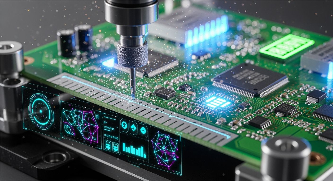
Picking the best pcba depaneling methods depends on many things. Consider shape, stress limits, build volume, and budget. Pick v-cut scoring for straight rectangular edges. It is a fast, low-cost pcb separation method. Choose tab-routing to cut tricky shapes safely. It keeps stress low on fragile ceramic parts. Use die punching for high-volume pcb manufacturing runs. It quickly separates thin, flex, or aluminum boards. Pick your depaneling choice early with pcb layout. This avoids board damage. It also lowers total manufacturing costs.
Key Takeaways
Pick V-cut depaneling for straight rectangular boards.
It saves money.
It also processes panels very fast.
Use tab-routing or lasers for curved shapes.
Lasers do not touch the board.
They protect delicate electronic parts from stress.
Choose heavy die punching for thin boards.
It works well for flex boards too.
It processes thousands of boards quickly.
Use it in high-volume factories.
Keep parts away from board edges.
Run strain gauge tests.
This stops component damage.
Quick Decision Framework for PCBA Depaneling Methods
You must check simple engineering facts. This helps select the best pcba depaneling methods. You need to check board shapes. Check the material strength too. Look closely at stress limits. Check the edge quality first. Then, pick your best pcb separation method.
Depaneling Technique | Key Application Scope | Induced Component Stress | Keep-Out & Clearance Requirements |
|---|---|---|---|
V-Cut System | Fast straight lines and rectangular cuts | Low (stays near the scoreline) | Needs a 1.5mm to 3.0mm clear zone |
PCB Router / Tab-Routing | Curvy shapes and mixed board layouts | Very Low (<250 µƐ) | Needs a 1.0mm to 3.0mm routing path |
Punching Die | Big factory runs with standard boards | Medium | Based on custom die size needs |
Tip: You can combine v-cut lines with routing. This trick works great for tricky panels. It saves raw materials. It lowers scrap waste too.
V-Cut Selection Criteria
Pick v-scoring for straight outer edges. This v-cut system uses top blades. It uses bottom blades too. Blades score straight grooves into FR-4 panels.
You build simple rectangular circuit boards.
Your panel layout has long straight lines.
You leave a 1.5mm to 3.0mm safe space.
A v-cut machine cuts straight lines fast. It costs very little money. Yet, v-cut vs tab-routing tests reveal facts. Harsh v-scoring stress damages ceramic parts.
Tab-Routing Selection Criteria
Use router depaneling for smooth curves. Use it for round circles. It works for wild outlines too. A CNC router cuts tiny tabs. It leaves very low stress behind.
You make non-rectangular pcb designs.
Delicate parts sit near board edges.
You want high precision. You want less dust.
Regular tab-routing needs a small gap. Keep a 1.0mm to 3.0mm path. Place it between separate boards.
Die Punching Selection Criteria
Set up punching dies for big runs. Special punching tools push thin boards out. They process flexible or aluminum boards fast. Modern plants also test laser depaneling. A cool laser beam cuts materials easily. It uses no physical force. This laser cut creates zero burrs. Clean laser heat protects small traces. It safely finishes tricky pcb depaneling jobs. Thermal laser depaneling keeps parts safe. It helps tight pcb depaneling work.
V-Cut Depaneling and V-Scoring Mechanics
Two round blades cut the board. Top and bottom blades cut together. They make thin grooves in the panel. This fast tool uses less material. It reduces panel waste a lot.
V-Scoring Depth and Residual Thickness
Set the right cut depth first. Keep the middle area strong. Leave one-third of the board thickness. Make double-sided grooves to do this.
Note: Rules say leave 33% board thickness. This keeps the board very strong.
Board Thickness | Groove Angle | Residual Web Thickness |
|---|---|---|
0.8 mm – 1.2 mm | 30° – 45° | 0.25 mm – 0.40 mm |
1.6 mm | 45° | 0.50 mm – 0.65 mm |
2.0 mm – 3.2 mm | 45° – 60° | 0.65 mm – 1.00 mm |
Good cut depth stops early breaks. Good depth makes final snapping easy.
Component Edge Clearance Guidelines
Blades make strong force near lines. Keep weak parts away from cuts.
Keep ceramic parts 1.0mm away.
Keep copper lines 0.4mm away.
Keep tall parts 2.0mm away.
Clear space stops small component cracks. Good designs ensure nice clean splits.
Mechanical Stress and Straight-Cut Limits
Cut v-cut lines in straight paths. Round wheels cannot cut curved shapes.
This process causes big mechanical stress. Breaking the middle line creates force. Never put cuts near weak parts. Boards under 0.6mm bend too much. Use straight lines across whole panels.
Tab-Routing PCB Depaneling Techniques
CNC Milling and Spindle Mechanics
Pick router depaneling for complex shapes. Fast CNC spindles turn milling bits. High speeds cut clean outer edges. Rapid tool spins reduce thermal stress. Compare laser beams with milling tools. Lasers quickly cut thin flex boards. Fast bits cut thick FR4 easily. Automatic routers yield clean board edges.
Operation / Feature | Recommended Spindle Speed | Recommended Feed Rate | Operational Notes |
|---|---|---|---|
General Machining / Traverse Cutting | 18,000–24,000 RPM | 30–60 IPM | High RPM lowers heat. It prevents board delamination. |
Initial Tool Plunge | 18,000–24,000 RPM | 15–20 IPM | Lower feed rates plunge thin boards safely. |
Tab Breakout Cuts | 18,000–24,000 RPM | 50% of normal feed rate | Cut retention tabs at half speed. |
Tab Layout and Mouse Bite Design
Place tiny breakaway tabs on layouts. Mouse bites assist quick pcb separation. Smart designs block early panel breakage. Evenly space small hole patterns.
Design Parameter | Recommended Baseline | Functional Impact |
|---|---|---|
Hole Diameter | 0.8 mm (Range: 0.5–1.0 mm) | Small holes leave smooth edges. |
Pitch Spacing | 2.0 mm (Range: 1.5–2.5 mm) | Close spacing risks early breaking. |
Edge-to-Edge Gap | 0.25 mm – 0.5 mm | Small gaps make tabs weak. |
Stress Mitigation and Tool Wear Trade-Offs
Router depaneling lowers mechanical stress. It shields small surface parts. Yet glass fibers dull bits quickly. Blunt tools damage thick copper traces.
Factories compare routers to lasers. UV laser beams never dull. Non-contact lasers cut fragile parts smoothly. Yet lasers cost more money. Laser tools complement physical router bits. Fiber lasers trim tight inner cutouts. Mechanical bits cut thick outer paths. Lasers stop burrs while bits save cash.
Punching and Die Cutting Depaneling
Pick die cutting for top output. Heavy press machines use high force. They push special tools through boards. This method separates boards very fast.
Custom Stamping Fixture Mechanics
Custom metal tools power die cutting. The system works in three steps:
Put special steel dies in presses.
Pressure locks the board flat.
The press cuts the board cleanly.
This method cuts flex and rigid boards. It will not hurt near parts.
High-Volume Production Speed
Die cutting works fast in factories. Place the full panel inside first. Sharp blades cut all edges at once. This action finishes in a second. Big factories love this fast method. You can process thousands of units hourly. This trick improves your production flow. It keeps all board edges clean.
Tooling Investment and Rigid Setup Limits
Custom steel tools cost a lot. Engineers design tools for one layout. You cannot change the set shape later. Use die cutting for fixed designs. Small builds cannot afford these tools. Other methods work better for changes. Compare tool costs before buying them.
V-Cut vs Tab-Routing and Punching Comparison
Mechanical Stress and Microstrain Risk
Track physical stress during pcb depaneling now. This step protects sensitive MLCC capacitors. Standard rules like IPC-9831 guide you. JEDEC-9704 rules suggest low strain levels. Keep strain under 500 microstrain total. High strain breaks internal ceramic layers fast.
Depaneling Method | Microstrain / Stress Level | Throughput Speed |
|---|---|---|
V-Cut | Moderate to High stress levels | Incredibly fast processing |
Routing | Moderate (<200 µstrain; can exceed 800-1000 µstrain with dull bits) | 50 to 100 mm/s cutting speed |
Punching | Low to Moderate stress (though generates high physical shockwaves) | Unmatched, massive output rate |
Manual v-cut blades create high localized strain. This happens during simple board separation. Router depaneling uses very sharp bits. It keeps strain under 200 microstrain. Yet dull router bits spike strain high. Strain can exceed 800 microstrain quickly. Laser depaneling uses thermal heat energy. It needs no physical cutting force. Non-contact laser cutting makes zero strain. It shields delicate trace layouts well.
Edge Quality and Burr Metrics
Each pcb separation method makes unique edges. Sharp v-scoring wheels make straight edges. They leave tiny fiber burrs behind. Milling router bits make smooth edges. Yet mechanical routing creates flying glass dust.
Die punching presses make clean lines fast. Yet punching dies leave rough burrs. This occurs on thick FR4 panels. Laser cutting makes super smooth edges. It leaves zero burrs on parts. Specialized UV laser depaneling stops delamination. It protects high-volume manufacturing runs easily. Non-contact laser cuts keep exact sizes. They prevent bad mechanical board shapes.
Tooling Costs and Scalability
Your build volume sets your budget. Cheap v-cut tools need low cost. They handle simple rectangular board arrays. Custom die punching tools cost more. High-speed punching yields massive factory outputs. This helps large manufacturing runs succeed.
Pro Tip: Combine v-cut lines and routing together. Smart hybrid layout improves panel use. It reduces scrap panel waste easily. It increases total factory yields too.
+-------------------------------------------------------------+
| Hybrid Panelization Layout                                  |
|                                                             |
| +-----------------------+     +---------------------------+ |
| | Board 1               |     | Board 2                   | |
| | (Straight edge)       |     | (Curved edge)             | |
| +-----------------------+     +---------------------------+ |
| =========== V-CUT LINE ==================================== |
| +---------------------------------------------------------+ |
| | Board 3 (Routing tabs cut outer irregular shapes)       | |
| +---------------------------------------------------------+ |
+-------------------------------------------------------------+
Engineers combine v-scoring with routing tools. This plan improves complete panel layouts. Run long v-cut lines through frames. This step boosts panel space usage. Use mechanical routing or UV lasers. Apply them to inner curved parts. Complex rigid-flex pcb setups need this. You can use punching dies. Try laser tools on thin flex sections. Meanwhile, standard routing cuts thick FR4. It trims rigid sections very safely.
Engineering Selection Criteria and DFM Rules
Geometry and Component Layout Rules
Good board layout cuts waste. Smart layouts boost build output. Keep parts away from edges. Follow these simple board layout rules:
Place parts 3mm to 5mm from v-cut lines.
Keep parts 3mm to 5mm from routing paths.
Keep copper lines 5mm from tabs. Avoid heavy parts near tab sites.
Leave 5mm to 7mm space for edge connectors.
Place weak parts far from break lines.
IPC Strain Gauge Testing Compliance
Test your pcb separation method using IPC/JEDEC-9704 rules. Test stress in four steps:
Pick a small strain gauge sensor.
Glue sensors near big BGA parts after reflow.
Record live force during pcb depaneling steps.
Check strain data through all build steps.
Volume Requirements and ROI Analysis
Build size sets the right depaneling plan. Simple layouts fit low-cost v-cut tools. They fit fast routing setups too. Fast v-cut scoring speeds up board splits. Heavy punching dies cost more early on. Yet punching processes big runs fast. Good layouts boost plant output. Smart layouts save material costs. Clean layouts help workflow. Right layouts protect parts.
Plants often pick laser depaneling tools. Smooth laser beams cut without force. Strong laser tools protect thin lines. A laser machine cuts tight shapes well. Soft laser cuts handle board updates. A laser system costs more upfront. Yet laser cuts stop broken parts. So laser depaneling helps long-term work. Good laser tools lower scrap waste. Picking laser depaneling keeps board quality high. Modern laser depaneling makes clean cuts.
Choosing good pcba depaneling methods takes care. Check board shapes first. Check stress limits too. Look at build volumes. Simple box designs use cheap v-cut tools. Delicate parts need soft laser systems. Laser tech cuts clean edges. A laser beam adds no force. Laser tools protect small pcb lines. Clever laser cuts with routing help layouts. A laser machine aids panel design. Smart panel rules save materials. Modern pcb depaneling plans raise output during pcb manufacturing.
Tip: Test designs with strain gauges. This step protects parts during manufacturing.
FAQ
How do you choose between v-cut and tab routing?
Check board shapes first. Use v-cut for straight lines. It is very cheap. Use router depaneling for wild shapes. It keeps physical stress low.
What is the main advantage of laser depaneling?
Laser depaneling cuts without touching boards. It makes no stress. This protects weak parts. A laser cuts wild designs well. Laser tools leave no burrs. Old dies leave rough edges.
When should you use v-scoring for pcb separation?
Use v-scoring for long straight lines. This pcb separation method lowers waste. It helps big factory runs. Keep weak parts away from lines. This stops bad board damage.
Why are factories switching to laser tools over routing?
Tip: A laser tool leaves no dust. Bits never wear out.
You pay less for tool fixes. A UV laser cuts flex boards. A green laser cuts small gaps. You reset a laser fast for updates.
Does thermal energy damage delicate circuit boards?
No. Smart light makes very little heat. You can use laser depaneling safely. It cuts fragile boards well. Quick pulses burn no small traces.
See Also
Top Five Advanced Testing Techniques For Through Hole Circuit Boards
Seven Vital Quality Inspection Stages In Through Hole Board Assembly
Choosing Between Full And Partial Turnkey Circuit Board Assembly Options
Complete Guide To Circuit Board Manufacturing And Final Assembly Testing
Understanding DIP Assembly Processes Quality Standards And Practical Industrial Uses
