Low-Loss Rogers PCB Materials for Advanced Electronics
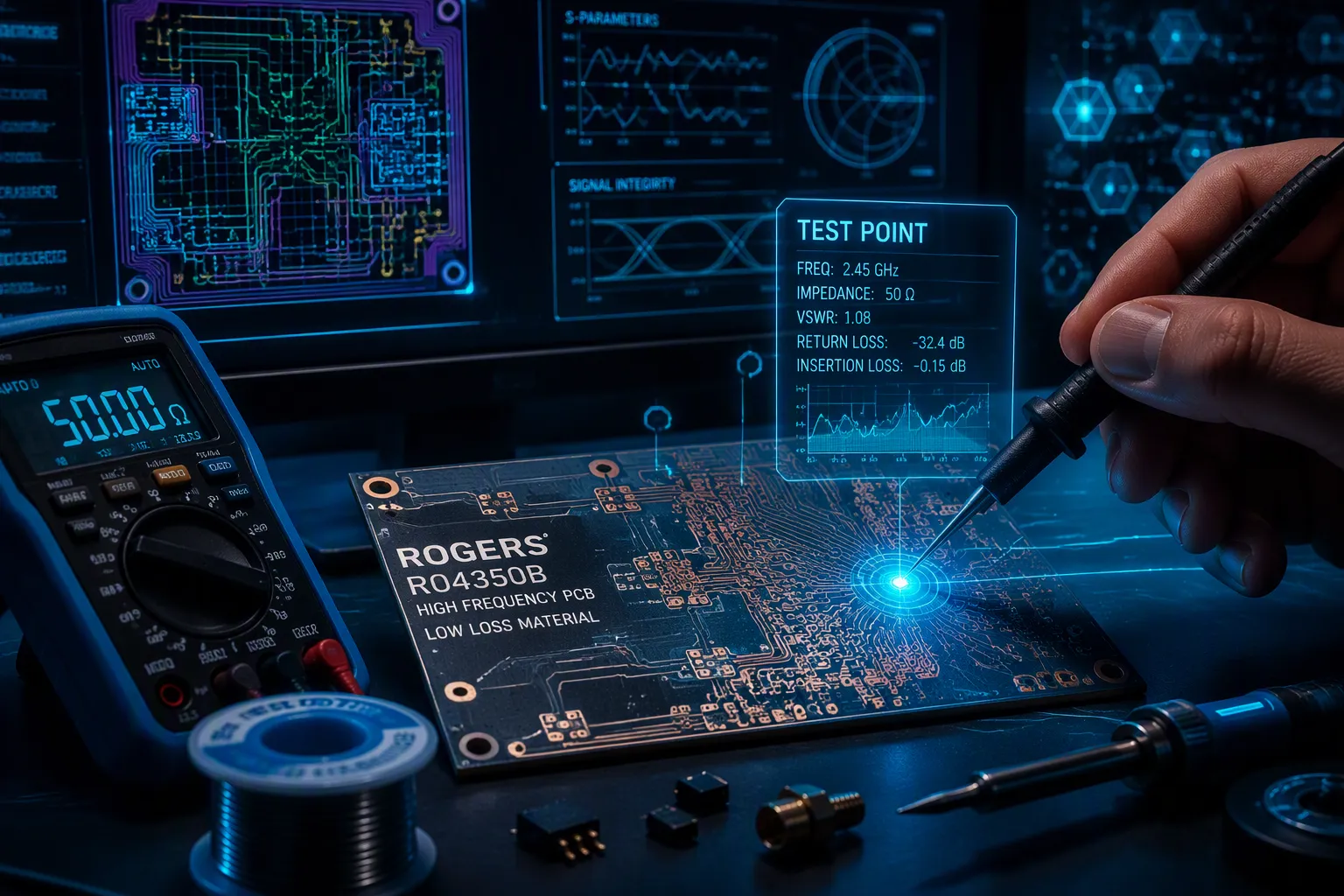
When standard FR4 fails at high-frequency uses, Rogers PCB materials give steady low-loss performance. These low-loss Rogers PCB materials are built for high-frequency circuits where signal quality is critical. At 10 GHz, they reach a dissipation factor of 0.002–0.004, while FR4 is at 0.02. That means five to ten times better loss. What makes these materials great for advanced electronics, and how do you pick the right one? This post explains key traits, benefits over FR4, common PCB material series, and selection tips. You will learn to choose the right high-performance circuit board for your RF designs.
Key Takeaways
Rogers PCB materials lose five to ten times less signal than FR4 at high frequencies. This helps your 5G, radar, and satellite designs work reliably.
The RO4000 series gives low-loss performance without a high price. It works like regular FR4, so it is a smart pick for designs from 8 to 40 GHz.
For tough conditions, use the RT/duroid or TMM series. They handle extreme temperatures and give very low loss for critical aerospace and defense circuits.
Switch from FR4 to Rogers materials when your circuit runs above 1 GHz. This change stops signal loss and keeps impedance steady across your board.
What Are Low-Loss Rogers PCB Materials?
Rogers PCB materials are special boards made for high-frequency circuits. They work well at speeds up to 110 GHz. Regular FR4 cannot handle these fast signals. Rogers materials use special resins and ceramic fillers to manage electrical behavior. You get steady results even when temperature or frequency changes.
Definition and Key Properties
Three main traits define a low-loss Rogers PCB material: low loss tangent, controlled dielectric constant, and thermal stability. The loss tangent (Df) shows how much signal energy turns into heat. Lower numbers mean less energy is wasted. The dielectric constant (Dk) controls how fast the signal moves through the material. Rogers keeps this value steady for exact impedance control.
Material | Dielectric Constant (Dk) | Dissipation Factor (Df) | Thermal Conductivity (W/m*K) |
|---|---|---|---|
RO3003 | 3 | 0.001 | 0.5 |
RO3006 | 6.5 | 0.002 | 0.79 |
RO4003C | 3.66 | 0.0031 | 0.71 |
RO4350B | 3.55 | 0.0021 | 0.69 |
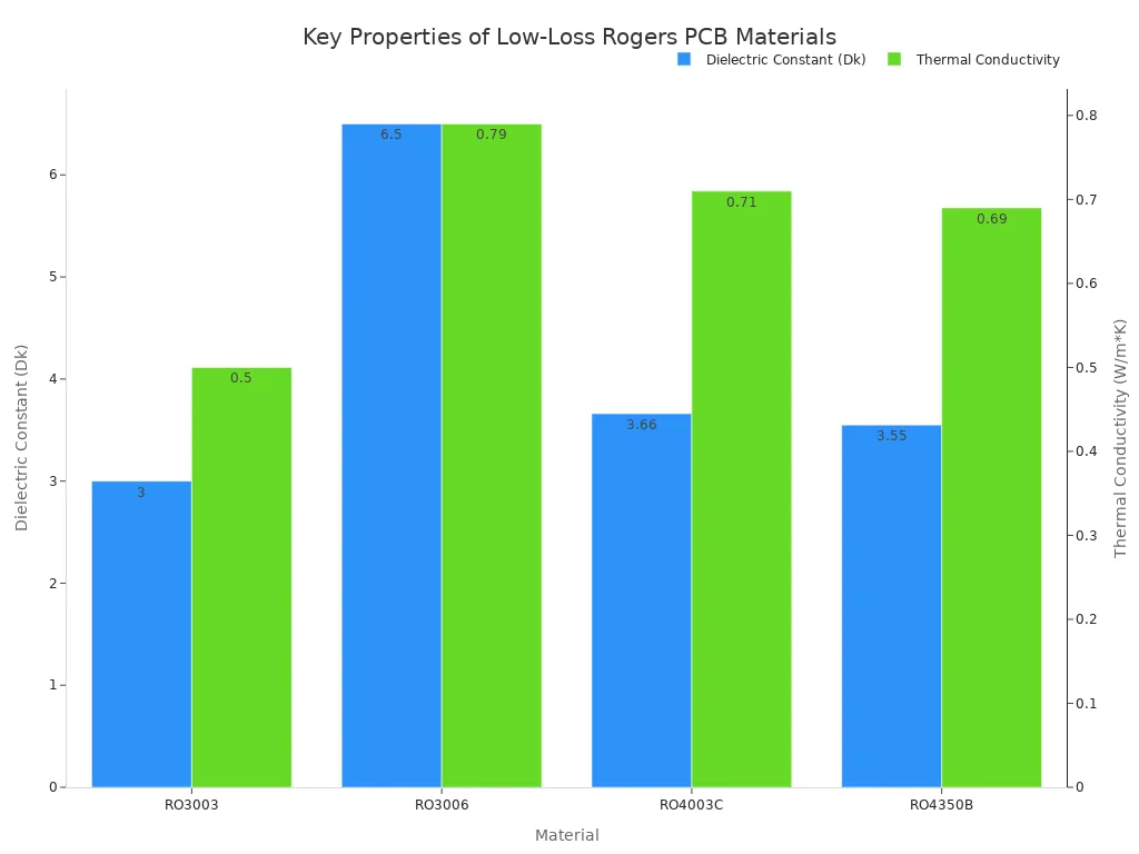
The RO4000 series has Dk values from 3.38 to 3.66. RO4003C is at 3.55, while RO4350B hits 3.66 at 10 GHz. These steady values let you design transmission lines with confidence. Heat handling matters too. RO4350B moves heat at 0.69 W/m/K, about twice as much as standard FR4. This strong heat control keeps circuits cool under heavy use.
Why Low Loss Matters in High-Frequency Circuits
Signal loss ruins performance in microwave and RF designs. Every inch of trace takes energy away from your signal. A bad material turns clean data into noise.
For a 50 ohm microstrip trace on standard FR4 (Df ~0.02) at 10 GHz, the insertion loss could be approximately 0.8-1.0 dB per inch. That loss is brought down to about 0.3 dB per inch with the same trace geometry on Rogers RO4003C (Df ~0.0027). That change over 6" of trace translates to over 4 dB of saved signal, and can be the difference between a successful or failed link budget.
This high-frequency laminate material cuts signal loss and distortion. You keep your signal clean and strong across the whole board. The RT/duroid 5880 goes even further with a dissipation factor of 0.0009 at 10 GHz.
The number that matters more is Df = 0.0009 at 10 GHz, holding tight through Ku and Ka-band.
Low signal loss means your system needs less boosting. You save power and reduce heat. For high-frequency uses like 5G, radar, and satellite links, this choice decides success. A rogers pcb material with low loss tangent keeps your signal clean from start to finish. You get minimal signal loss even at millimeter-wave speeds. This high-performance material gives you an edge in tough RF settings.
Rogers PCB vs. FR4: When to Choose High-Frequency Materials
Choosing between standard FR4 and a rogers pcb depends on your operating frequency and performance needs. FR4 works fine for simple digital boards and low-speed circuits. But once you push past certain limits, the material itself becomes your biggest problem. Understanding the differences helps you make the right call for your design.
Dielectric Constant and Loss Tangent Comparison
The loss tangent (Df) shows how much signal energy turns into heat inside the material. Lower numbers mean cleaner signal transmission. Here is how the two materials compare:
Material | Loss Tangent (Df) |
|---|---|
Standard FR4 | ~0.02 |
Rogers RO4350B (RO4000 series) | 0.0037 |
FR4 has a loss tangent of 0.02, while RO4350B has 0.0037, meaning FR4 loses about five times more signal energy inside the material. That difference grows even larger at higher frequencies. At 10 GHz, Rogers 4350B maintains a loss tangent of 0.0037, while FR4's loss climbs steeply. This gap directly affects your signal integrity.
Standard FR4 laminates are suitable for operation up to 1 GHz. Above this frequency, the material's high dielectric loss (Df ≈ 0.02) and unstable dielectric constant (Dk) cause excessive signal attenuation, crosstalk, and timing errors, making signal degradation unacceptable for most digital and RF applications.
The dielectric constant (Dk) matters just as much. FR4's Dk shifts with temperature and frequency, which causes impedance mismatches. A rogers pcb material holds its Dk steady across a wide frequency range. This stability gives you precise impedance control for transmission lines. You can design matching networks and filters with confidence because the material behaves predictably.
For systems operating at 3 GHz or higher, such as 5G infrastructure, FR4 is no longer viable. The maximum acceptable operating frequency for FR4 sits at approximately 1 GHz. Beyond that point, you need a high-frequency laminate. A low-loss rogers solution delivers the consistent electrical behavior your circuit demands.
Thermal and Mechanical Performance Differences
Heat affects circuit performance in ways you cannot ignore. FR4 has a glass transition temperature (Tg) between 130 and 180°C. When the board exceeds this temperature, the material softens and changes dimension. Traces shift, vias crack, and your signal paths degrade.
Material | Glass Transition Temperature (Tg) (°C) |
|---|---|
Standard FR4 | 130 to 180 |
Rogers 4000 series | ~280 |
Rogers 4000 series materials have a glass transition temperature close to 280°C, confirming that their thermal performance is significantly higher than standard FR4. This means a rogers pcb can handle higher operating temperatures without warping or losing structural integrity. You get excellent thermal stability even under heavy power loads.
Mechanical properties differ too. FR4 absorbs moisture more readily, which changes its electrical characteristics over time. Rogers materials resist moisture absorption, keeping their dielectric properties stable in humid environments. This consistency matters for outdoor microwave installations and automotive radar systems.
The thermal conductivity of Rogers materials also exceeds FR4. Better heat spreading means your board runs cooler. Components stay within their rated temperatures, extending their lifespan. For high-power RF amplifiers and antenna arrays, this thermal performance directly impacts reliability.
When you compare costs, FR4 wins on price per square foot. But consider the total system cost. A board that fails in the field costs far more than the material savings. For high-frequency applications above 1 GHz, the choice becomes clear. You need a high-performance material that maintains signal quality and withstands thermal stress.
Your decision ultimately depends on three factors: operating frequency, thermal environment, and budget. If your design runs below 1 GHz with modest thermal demands, FR4 may suffice. For microwave circuits, 5G systems, or radar applications, a rogers pcb material provides the low signal loss and stable impedance you need. The extra cost pays for itself through better performance and fewer field failures.
Key Rogers PCB Material Series for Advanced Electronics
When you design a high-frequency pcb, you need the right material. Rogers offers two main families. The RO4000 series balances cost and performance. The RT/duroid and TMM series target extreme environments. Understanding both helps you choose wisely.
Rogers RO4000 Series for Cost-Effective High-Frequency Designs
The RO4000 series gives you low-loss rogers performance without the high cost of PTFE-based laminates. This high-frequency laminate material works well from 8 GHz to 40 GHz. You get a dissipation factor as low as 0.0021 for RO4350B at 10 GHz. This keeps your signal clean across the board.
One major advantage is fabrication. This rogers pcb material processes like standard FR4. You do not need special equipment or extra steps. This makes manufacturing faster and cheaper. The ceramic fill does cause faster bit wear during drilling, but the overall process flow stays the same. You also need to account for etch compensation to get the right impedance.
The RO4000 series is "FR4-like" in manufacturing complexity. Use RO4000 when you need FR4-like processing with RF Dk.
The cost difference tells the story clearly.
Laminate Type | Cost Relative to FR-4 |
|---|---|
Rogers RO4000 series | 3 to 5 times |
PTFE-based (e.g., RT/duroid 5880) | 10 to 15 times |
RO4000 costs three to five times FR4. PTFE-based laminates cost ten to fifteen times FR4. That gap makes RO4000 a smart choice for many designs. You get the rf performance you need without paying for expensive PTFE processing.
You can use this rogers pcb in many applications:
Carrier-Grade Wi-Fi
Communications Systems
Computing
IP Infrastructure
Phased Array Radar Systems
Power Amplifiers
Small Cells
Test & Measurement
Each application requires stable impedance and low loss. The RO4000 series delivers both. Whether you build a 5G small cell or a radar system, this material gives you consistent results.
The RO4000 series also gives you excellent thermal stability. The glass transition temperature reaches about 280°C. This keeps your board stable under heat. You get precise impedance control because the dielectric constant stays steady across frequency. For many high-frequency designs, this rogers pcb material offers the best balance. You get good performance without the high cost or complex fabrication.
RT/duroid and TMM Series for Extreme Environments
When your design faces harsh conditions, you need the RT/duroid and TMM series. These materials use ceramic-filled PTFE. They deliver very low loss and stable performance in extreme temperatures. The loss tangent can go as low as 0.0009 for some grades. This makes them ideal for critical microwave circuits.
The RT/duroid series offers a wide range of dielectric constants. You can choose the right Dk for your rf and microwave applications.
Product Series | Dielectric Constant (Dk) |
|---|---|
RT/duroid 5880LZ | 2.0 |
RT/duroid 5280LZ | 2.06 – 2.10 |
RT/duroid 5880 | 2.20 |
RT/duroid 5870 | 2.33 |
RT/duroid 6002 | 2.94 |
RT/duroid 6202 | 2.94 – 3.06 |
RT/duroid 6035HTC | 3.6 |
RT/duroid 6006 | 6.15 |
RT/duroid 6010.2LM | 10.2 |
The Dk range goes from 2.0 to 10.2. This gives you flexibility for different designs. Low Dk materials work well for high-speed signals. High Dk materials help you reduce board size. This rogers pcb gives you precise impedance control across the entire range. You can match your transmission line needs exactly.
The TMM series adds another option. TMM10 laminate has a thermal conductivity of 0.76 W/m·K. This is about twice that of traditional PTFE/ceramic laminates. Better heat transfer means your board stays cooler under power. This matters for high-power amplifiers and radar systems. The TMM series uses thermoset resin instead of PTFE. This gives you better mechanical stability. You can drill and plate these materials like standard boards.
These materials suit applications like aerospace, defense, and satellite communications. You get reliable performance where other materials fail. The low loss tangent keeps your signal strong even at millimeter-wave frequencies. This makes them ideal for high-speed industrial electronics.
For extreme environments, the RT/duroid and TMM series deliver. This high-performance rogers pcb material handles temperature swings, vibration, and moisture. Choose these when your design cannot afford failure.
Rogers PCB materials keep signal integrity where regular FR4 fails above 1 GHz. Each series has a different purpose. The RO4000 family balances cost and performance for 8-40 GHz. The RT/duroid and TMM series handle extreme environments and have ultra-low loss tangents.
Your choice depends on three things: operating frequency, heat needs, and budget. A Rogers PCB material with stable dielectric constant gives exact impedance control. The right high-frequency laminate stops signal loss and lowers system power needs.
Rogers has two main types for advanced designs. Pick a Rogers material that fits your heat and frequency needs. Review the datasheets for each Rogers PCB series before deciding. Ask manufacturers about your RF uses. They can help you find the best material for your design.
FAQ
How Much More Does a Rogers PCB Cost Than FR4?
A rogers pcb costs three to fifteen times more than FR4. The RO4000 series costs three to five times as much. PTFE-based options like RT/duroid cost ten to fifteen times more. You pay for lower loss and steady impedance. Think about your frequency needs before you choose.
Which Rogers Material Should You Pick for Your Design?
Pick RO4000 for 8-40 GHz uses when you have a budget. It is made like FR4 and works well for RF. Choose RT/duroid or TMM for tough conditions. These materials handle heat and deliver very low loss. Match the material to your working frequency and heat needs.
Does a Rogers PCB Require Special Fabrication Steps?
The RO4000 series is made like standard FR4. You do not need special tools. The ceramic fill makes drill bits wear out faster. You also need to adjust etching to get exact impedance. PTFE-based materials need more careful work. Always work with a maker who knows high-frequency laminates.
When Should You Switch From FR4 to Rogers Materials?
Switch when your design works above 1 GHz. FR4 loses signal quality at those speeds. A rogers pcb keeps your signal clean and impedance steady. You also get better heat handling. For microwave circuits, 5G, or radar, the upgrade pays off with fewer failures and better performance.
See Also
Essential Raw Materials Required For PCBA Manufacturing Processes
Ensuring High Quality Output In Modern Turnkey PCBA Facilities
Sourcing Electronic Parts For Efficient PCBA Production Lines
Designing PCB Layouts To Meet SMT Assembly Manufacturing Standards
Choosing Appropriate PCB Substrates For Surface Mount Assembly Operations
