How to Use Boundary Scan Testing for Effective PCBA Debugging
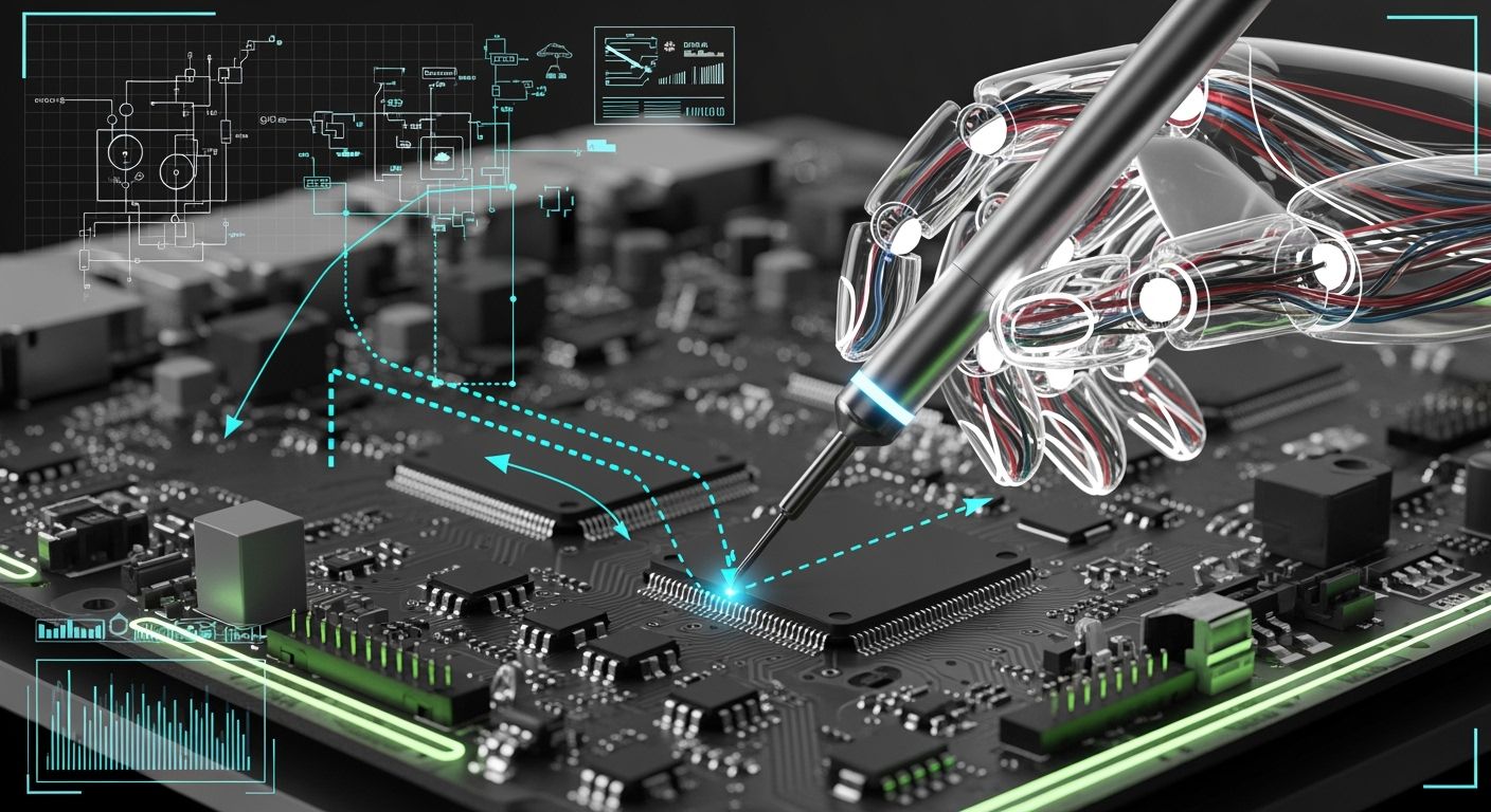
You can use boundary scan testing to fix pcb assemblies fast and well. You can do this even if you cannot touch every pin. Boundary scan helps you check connections and find hidden problems on tricky boards. It works best for boards with BGAs. You do not need to use physical probes. This keeps testing safe and does not harm your board. The table below shows how boundary scan makes your testing better:
Benefit | Description |
|---|---|
Non-intrusive testing | Checks electrical connections without touching the board. This is important for crowded boards. |
Fault detection | Finds hidden solder problems and connection issues. |
Faster fault isolation | Helps you find faults on certain pins or nets faster. |
Better diagnostics | Gives results linked to device pins, not just unclear signs. |
Lower fixture complexity | Makes test setups simpler and easier. |
Reusable test logic | Lets you use testing chains again for new board versions. |
Improved production throughput | Less manual probing makes production go faster. |
Key Takeaways
Boundary scan testing lets you check PCB connections without using probes. This makes it safe for boards with many parts.
This method finds hidden problems like shorts and opens fast. It helps you debug faster and with better accuracy.
Using boundary scan can lower testing costs a lot. You do not need many costly fixtures and test points.
If you use boundary scan with other tests, you find more faults. This makes your diagnostics more complete.
Design your board with boundary scan in mind. This helps you test better and faster.
Boundary Scan Testing Overview
What Is Boundary Scan?
Boundary scan helps you test and fix printed circuit board assemblies without touching them. This way, you can check every pin and connection, even if you cannot reach them with probes. It works well for boards with BGAs and other crowded parts. You can use boundary scan to watch pins, check voltages, and test how things connect. Here are some main things boundary scan testing does:
You save money on making tests because you use a simple way to control input and output pins.
You do not need to buy costly fixtures, which helps when making and testing boards.
You finish testing faster than with other ways.
You get clear fault details, so you can find and fix problems early.
Boundary scan helps you find problems like open circuits, short circuits, and parts put in the wrong place. You can also find soldering problems and missing connections that are hard to see with old tools.
JTAG Standard Explained
JTAG is the rule that lets boundary scan work. You use JTAG to test how things connect on PCBs and chips without using probes. Each pin on a chip has a boundary scan cell. These cells let you control and watch signals at the pins. You can run tests outside (EXTEST) and inside (INTEST) the chip’s logic. The JTAG rule uses a Test Access Port (TAP) and a state machine to run the tests. Here is a table that shows the main parts of JTAG:
Component | Description |
|---|---|
IEEE 1149.1 Standard | Makes the rules for boundary scan testing on chips and boards. |
Test Access Port (TAP) | Runs the boundary scan with a state machine that has 16 states. |
Boundary Scan Architecture | Lets you test how chips connect without using test leads. |
Instruction Register | Holds commands for boundary scan jobs. |
Test Data Registers | Keep things like chip IDs and test data. |
JTAG testing lets you change what pins do and check signals across lines. This makes it easier to find problems in tricky boards.
Boundary Scan vs. Traditional Debugging
You might wonder how boundary scan is different from old debugging ways. With old probe-based ways, you often miss problems in crowded or hidden spots. Boundary scan testing is good at finding open circuits, short circuits, stuck-at faults, and soldering problems. You can also find missing or wrong connections, which happen a lot in crowded boards. Old ways have trouble with these problems, especially when you cannot reach the pins. Boundary scan testing gives you a clear look at the hardware’s health and helps you keep quality high when making boards.
Note: Over 70% of new electronic designs now use boundary scan features. People want better testing as boards get more complex.
Boundary Scan Testing Setup
Setting up a boundary scan test system helps you debug your PCBA without touching the board. You can follow these steps to get started and make sure your testing is fast and safe.
JTAG Hardware Requirements
You need the right hardware to use boundary scan. Each part plays a key role in making your testing work well. Here is a table that shows what you need:
Component Type | Description |
|---|---|
IEEE 1149.1 compliant ICs | These components are designed to allow boundary scan tests. |
Test bus connector | Should be placed at the edge of the PCB for accessibility. |
JTAG test access ports (TAPs) | Typically laid out in a daisy chain along the test bus, facing the test bus to minimize vias. |
You should check your board for these parts before you start. Place the test bus connector where you can reach it easily. Arrange the TAPs in a daisy chain to keep the setup simple. This setup lets you avoid using physical probes, which keeps your board safe from damage.
Tip: Always check the datasheets and vendor documents for each device. This helps you confirm that your devices support boundary scan.
Boundary Scan Software Tools
You need software to control your boundary scan test system. Many tools help you run tests, program devices, and see results. Intel's boundary-scan tool works well for boards with tight lead spacing. It tests pin connections without using probes and can program Intel FPGA devices while they are on the board. Intellitech's Eclipse offers high fault coverage, easy integration with other tools, and can test many units at once.
Here is a table that compares some features:
Feature | Intellitech's Eclipse | Intel's Boundary-Scan Tool |
|---|---|---|
Test Development | Yes | Yes |
Concurrent JTAG Test | Yes | No |
On-board JTAG FLASH Programming | Yes | No |
Logical Design Viewer | Yes | No |
Interconnect Test Generation | Yes | Yes |
In-system Programmability | No | Yes |
Support for Multiple UUTs | Yes | No |
Automated Memory Interconnect Testing | Yes | No |
You can pick the tool that fits your needs. Some tools let you test many boards at once. Others focus on programming or special chip features.
Note: Many software tools let you capture data while the device works normally. This helps you find problems without stopping the board.
Running Boundary Scan Tests
You can run boundary scan tests in a few simple steps. Follow this order to make sure you get good results:
Connect your testing equipment to the board. Send the signal to the TDI input pin.
The signal moves through the input pin to the logic cells and then to the core logic.
Scan the signal at the core logic. Shift the output through the TDO pin.
Compare the output with the expected result. This helps you find faulty parts and defects.
Set the cells for external or internal testing. This lets you check both chip logic and how things connect.
You do not need to use physical probes during these steps. The boundary scan cells handle the data for you. This makes the process non-invasive and safe for your board.
Tip: Validate your scan chain early. This helps you avoid problems later in production.
Analyzing Results
After you run your tests, you need to look at the results. Boundary scan testing uses special cells to capture data from each pin or logic signal. You can compare the real results with what you expect. This helps you spot problems like shorts, opens, or pin faults.
Here is a table that shows common faults you might find:
Fault Type | Description |
|---|---|
Shorts | Electrical connections between nets that are not supposed to connect. |
Opens | Breaks in the circuit that stop current from flowing. |
IC pin faults | Problems with the pins of chips that affect how they work. |
Missing pull resistors | Resistors that should be there but are missing, causing circuit issues. |
You can use the software to highlight these faults. The tool will show you which pin or net has a problem. This makes it easy to fix the board and keep your production moving.
Boundary scan checks connections without using probes.
It uses cells to capture and drive data.
You can find faults like shorts and opens quickly.
Note: Keep your documentation up to date. This helps you track changes and makes debugging easier.
Boundary Scan Integration Tips
Handling Non-JTAG Devices
You may find some devices on your board that do not support jtag. These parts can make boundary scan more challenging. You can still test these areas by using special test points or by designing your board with extra connections. Sometimes, you can use cluster testing. This method checks groups of non-jtag devices by controlling them through nearby boundary scan devices. You should always plan for these cases during your design phase. This helps you avoid missing faults in important parts of your board.
Combining Boundary Scan with Other Methods
You can get the best results when you combine boundary scan with other testing methods. In-circuit testing checks if each part works by itself. Functional testing looks at how the whole board performs. When you use boundary scan together with these methods, you cover more faults. You make sure each part works and the whole system runs well. This approach gives you strong fault coverage and helps you catch problems early.
Here are some tips for combining these methods:
Plan your tests during the design stage so all methods work together.
Keep your testing equipment calibrated for accurate results.
Use data from your tests to improve your process over time.
Boundary scan works well for boards with high part density or limited access. You can reach hidden faults that other methods might miss.
Common Pitfalls
You may run into some common problems when using boundary scan. If you forget to check device datasheets, you might miss out on important features. Skipping scan chain validation can lead to wasted time during debugging. Not updating your test plans as your board changes can cause confusion. You should always keep your documentation current. This helps you track changes and makes future testing easier.
Tip: Review your test setup often. This helps you catch mistakes before they slow down your project.
You can avoid most pitfalls by planning ahead and following best practices for boundary scan.
Boundary Scan Testing Benefits
Fault Coverage
You want to catch every possible problem on your pcb assemblies. Boundary scan gives you a way to check connections that you cannot reach with normal probes. This is very important for boards with BGA or fine-pitch parts. You can use boundary scan to look at solder joints and find both open and short circuits. Traditional testing methods often miss these issues, but boundary scan testing lets you see inside the board’s connections. You get a clear view of digital nets and can spot broken or missing links. This makes your diagnosis more accurate and helps you fix problems before they reach your customers.
Debugging Speed
You can save a lot of time with boundary scan. When you use jtag, you do not need to set up many test points or move probes around. This method works well for high-density boards and complex parts. Here are some ways boundary scan helps you work faster:
You can test BGAs and fine-pitch devices with ease.
You find faults quickly, which can cut production time by up to 60%.
You can detect up to 95% of interconnect faults on jtag-compliant devices.
You switch between normal and test modes without stopping the board.
Boundary scan gives you fast fault diagnosis and helps you keep your production line moving. You do not waste time searching for hidden problems.
Cost Efficiency
You can lower your costs by using boundary scan. You do not need to buy expensive test fixtures or add many test points. Companies have saved up to $50,000 per fixture by switching to this method. You also get better test coverage with fewer tools. The table below shows some key ways boundary scan improves your bottom line:
Benefit Type | Description |
|---|---|
Cost Savings | You save money by reducing the number of test fixtures needed. |
Efficiency | You need fewer test points, which lowers setup costs and increases coverage. |
Production Output | You find faults early, which leads to higher product yield and quality. |
You can reuse test patterns for different boards, which saves even more time and money. Boundary scan testing helps you deliver better products at a lower cost.
You can use boundary scan to check new hardware. It helps you test boards that are not finished yet. You can also use it to program devices. Boundary scan lets you find problems in how things are put together. You can make sure your hardware works before adding firmware. In factories, boundary scan helps test and fix boards fast.
Design engineers use boundary scan to check and start new boards.
Test engineers make tests for fixing and building boards.
People in production use boundary scan for quick and trusted results.
Plan for boundary scan when you start your design. This helps you get the best results from your testing.
FAQ
What is boundary scan testing?
Boundary scan testing lets you check connections on a PCB without touching the board. You use special cells in chips to control and monitor pins. This method helps you find faults quickly.
Why should you use boundary scan for BGAs?
You cannot reach BGA pins with probes. Boundary scan lets you test these hidden pins. You find solder faults and connection issues without damaging the board.
Do you need special software for boundary scan?
Yes. You need boundary scan software to run tests and analyze results. The software helps you control devices and see faults. Many tools work with different boards.
Can you test non-JTAG devices with boundary scan?
You can test some non-JTAG devices by using cluster testing. You control these parts through nearby JTAG devices. Plan your board design to include extra test points.
How does boundary scan save you money?
Reason | How it helps you |
|---|---|
Fewer fixtures | You do not buy expensive tools |
Faster testing | You finish tests quickly |
Reusable logic | You use test patterns again |
See Also
PCBA Services: Comprehensive Coverage from Production to Testing
Essential Strategies to Enhance PCBA Reliability Over Time
The Role of X-Ray Inspection in PCBA Quality Assurance
