Technical requirements for wave soldering in DIP assembly processing
Wave soldering in DIP assembly needs careful work and rules.
Place components correctly to avoid mistakes.
Use the right solder temperature for good results.
Check if materials work well together.
These steps help make strong connections and reduce problems.
Key Takeaways
Placing parts correctly is very important. Line them up right and check polarity to stop expensive errors during assembly.
Watch soldering temperatures closely. Preheat between 160°C and 170°C, and keep solder bath heat between 245°C and 265°C for strong bonds.
Take care of soldering tools often. Clean and inspect machines every day to get good results and avoid problems.
Understanding the Wave Soldering Process
Flux Application
Flux is important in wave soldering. It cleans metal surfaces and stops rust. Make sure flux covers all soldering areas evenly. You can apply it using spray, foam, or wave methods. This step helps make strong solder joints and avoids problems like gaps or extra solder.
Preheating
Preheating helps parts handle heat better and activates flux. The temperature is usually between 90°C and 110°C. Keeping it around 160°C to 170°C improves solder flow and reduces mistakes. But going over 180°C can ruin the flux and cause bad soldering. Watch the preheating closely for the best results.
Solder Wave Parameters
The solder wave is the main part of this process. Things like wave height, speed, and flux amount need to be just right. The wave height should touch the PCB pads properly. Experts suggest a flux speed of 45 psi and air pressure of 25 psi. These settings help make good solder joints and avoid errors.
Cooling
Cooling hardens the solder and makes it strong. Fast cooling after soldering creates solid bonds. But cooling too long can cause cracks or holes. Controlled cooling lowers stress and makes solder joints last longer. A solder bath temperature of 245°C to 265°C works best for good results.
Key Technical Requirements for DIP Assembly in Wave Soldering
Component Orientation and Placement
Placing components the right way is very important. Make sure parts are lined up correctly, with polarity marks easy to see. This helps avoid mistakes during assembly and checking. Keep at least 125 mils of space between parts and the board edge. This spacing lowers stress and stops damage to the PCB.
Tip: Always check polarized parts like diodes and capacitors before soldering. Wrong placement can cause failures and expensive fixes.
PCB Layout Considerations
The PCB design affects how well wave soldering works. Follow these rules for better results:
Use drilled hole sizes and spacing that match your fabricator’s tools.
Keep clearances that work with your manufacturer’s limits.
Leave enough space near board edges to avoid soldering problems.
Shape the board for easy penalization.
Add thermal reliefs to control heat during soldering.
Spacing is also very important. Keep at least 125 mils between parts and the board edge for smooth soldering.
Note: A good PCB design reduces problems like solder bridging and makes the assembly more reliable.
Soldering Temperature Profiles
Temperature control is key for strong solder joints. Watch preheat, solder wave, and cooling temperatures closely. Preheat temperatures should match flux needs to activate it and prepare the PCB. Too much heat can cause shorts, while too little leaves residue.
During soldering, keep the bath temperature between 245°C and 265°C. This range helps solder flow well and makes strong connections. Cooling after soldering should be controlled to stop cracks and make joints last longer.
Tip: Use machines to check and adjust temperatures for steady results.
Material Compatibility
Choosing the right materials is very important for wave soldering. Make sure the flux, solder alloy, and PCB materials work well together. Here’s a quick guide:
Aspect | Details |
|---|---|
Flux Types | Rosin (RO) and Resin (RE) with activity levels from L0 to L1. |
Solder Alloys | Sn60Pb40, Sn62Pb36Ag2, Sn63Pb37, Sn96.3Ag3.7 are recommended. |
Testing Requirements | Test flux and solder paste to check compatibility. |
Preheat temperatures must match flux needs. Too much heat can cause shorts, while too little leaves residue. Picking the right materials and testing them helps avoid problems like rust and dirt.
Tip: Ask your PCB assembly provider for advice on material choices. LT PCBA offers expert help and testing to guide you.
Common Problems in Wave Soldering and How to Solve Them
Solder Bridging
Solder bridging happens when solder connects nearby pins by mistake. This creates a short circuit. It usually occurs due to too much solder, wrong wave height, or bad PCB design.
Problems Caused by Solder Bridging:
Pins get connected, causing electrical shorts.
Solder skips some joints, leaving them incomplete.
To fix this, adjust the solder wave height and speed. Make sure the PCB design has enough space between pins. Use Automated Optical Inspection (AOI) to find solder bridges early. This reduces manual fixes. Adding rework steps to your process lowers waste and boosts efficiency.
Tip: Check soldering machines often to keep wave settings steady and avoid problems.
Weak Solder Joints
Weak solder joints make parts connect poorly to the PCB. This can cause failures. It often happens due to wrong soldering temperatures, not enough flux, or poor wetting.
Metric | Value |
|---|---|
≥ 98% | |
Defects Per Million Opportunities (DPMO) | ≤ 500 |
To avoid weak solder joints, watch the soldering temperature carefully. Preheating should activate the flux and prepare the PCB. Use AOI to check solder joint shapes and ICT to find issues with impedance. Sample testing and X-ray checks can also spot hidden problems.
Note: Adjust the heat profile for each part type to stop cold joints or cracks.
Misaligned Parts
Misaligned parts can make the PCB not work properly. This happens when parts are placed wrong or wave soldering settings are off. Misalignment can cause open circuits or weak connections.
To solve this, check part placement and direction before soldering. Use tools or machines to align parts correctly. Change conveyor speed and wave height to stop parts from moving during soldering.
Tip: Always check the direction of parts like diodes and capacitors to avoid costly mistakes.
Oxidation and Dirt
Oxidation and dirt are big problems in wave soldering. Oxidized surfaces stop solder from sticking well, making weak joints. Dirt like organic residue can also lower solder quality.
Analysis Type | Findings |
|---|---|
SEM-EDS | High Carbon and Oxygen levels in bad solder areas, showing contamination. |
FTIR | Similar to 'Flux after reflow', meaning organic residue affects solder. |
To fix oxidation, keep the soldering area clean and free of dirt. Use flux to clean metal surfaces before soldering. Store parts and PCBs properly to stop oxidation.
Note: Cooling solder carefully after soldering lowers stress and stops defects like solder icicles caused by oxidation.
Best Practices for Wave Soldering with LTPCBA
Optimizing Flux Application
Applying flux the right way is very important. Make sure the flux spreads evenly on the PCB to clean metal and stop rust. The Wave Soldering Guide says to adjust flux thickness and avoid using too much. Tools like spray nozzles and infrared sensors help apply flux correctly. These steps make solder joints stronger and reduce mistakes.
Adjusting Preheating and Solder Wave Settings
Setting preheating and solder wave correctly is key for good results. Preheating gets the flux ready and prepares the PCB for soldering. Research shows keeping preheating at 170°C and soldering at 250°C works best. The table below shows important settings for better control:
Factor | Importance Level | Best Setting |
|---|---|---|
Preheating Temperature | High | 170°C |
Track Speed | Medium | 1050 mm/min |
Soldering Temperature | High | 250°C |
Flux Type | High | HF28 |
These settings help avoid problems like weak joints or solder bridges.
Ensuring Proper PCB Design
A good PCB design makes wave soldering easier. Keep enough space between parts and the board edge to prevent soldering issues. Adding thermal reliefs spreads heat evenly and lowers stress on solder joints. Working with your PCB assembly provider, like LTPCBA, ensures your design fits their tools and improves reliability.
Regular Maintenance of Equipment
Taking care of your soldering equipment keeps it working well. Daily tasks include cleaning flux systems, checking solder pots, and confirming temperatures. Weekly and monthly tasks involve deep cleaning, calibration, and performance checks. The chart below shows how often to do these tasks:
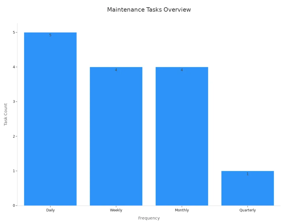
Regular maintenance prevents breakdowns and keeps results high-quality.
Wave soldering needs careful work and following rules. Focus on placing parts correctly, designing the PCB well, and controlling temperatures. LTPCBA helps with expert tips and modern tools. Using these methods makes soldering stronger, reduces mistakes, and ensures it lasts longer.
FAQ
What is the best temperature for wave soldering?
The best temperature is between 245°C and 265°C. This helps solder flow well and makes strong connections without harming parts.
How do you stop solder bridging in wave soldering?
To stop solder bridging, adjust the solder wave height. Also, design the PCB with enough space between pins.
Tip: Use Automated Optical Inspection (AOI) to find solder bridges early. This reduces the need for fixing them by hand.
Why is preheating needed in wave soldering?
Preheating gets the flux ready and prepares the PCB for soldering. It also lowers heat stress, making solder joints better.
Note: Keep preheating temperatures between 160°C and 170°C for the best results.
See Also
Understanding SMT And DIP Assembly In PCBA Processes
Essential Criteria For PCB Boards In SMT Manufacturing
Important Aspects Of DIP Assembly Techniques Explained