Technical precautions for HDI PCB surface mount assembly
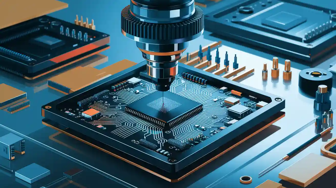
In HDI PCB assembly, technical precautions are essential as careful steps lead to better and more reliable results. You deal with small parts and close spaces, which require exact methods to avoid mistakes. By using the right techniques, you can ensure that parts work well and lower risks, ultimately making the product more dependable.
Key Takeaways
Use accurate tools to place small parts correctly in HDI PCB. This lowers errors and makes it more reliable.
Manage heat carefully during soldering to make strong connections. Avoid harming parts by setting the right temperature for materials.
Follow strict quality checks, like inspections and certifications, to keep HDI PCB production at high standards.
Common challenges in HDI PCB surface mount assembly
Smaller parts and close spacing
Smaller parts are harder to place on PCBs. Close spacing makes placement mistakes more likely. Problems like solder bridges and tombstoning happen often with tiny parts.
Report Title | Summary |
|---|---|
Area Array Placement Yield Prediction | Shows how simulations help find placement problems in small parts. |
Warpage Modeling And Measurement | Explains how tiny parts affect assembly success and reliability. |
To fix these issues, use better placement tools and align parts carefully.
Controlling heat during soldering
Heat is important for soldering but too much can harm parts. Good heat control makes strong solder joints without damage. Use materials that spread heat well and adjust soldering heat levels for balance.
Picking the right materials
Choosing good materials helps HDI PCBs work well. Think about things like heat, signal loss, and how materials expand. For example:
Metric | Description |
|---|---|
Glass Transition Temperature (Tg) | Helps materials stay strong under heat. |
Thermal Conductivity | Spreads heat better in high-performance uses. |
Using the right materials makes PCBs last longer and lowers risks.
Signal quality and high-frequency problems
Fast signals in HDI PCBs need extra care. Things like trace width and material properties affect signal quality. Thinner layers bring ground planes closer, improving signals. Adjust materials like copper to make signals better.
Common defects like solder bridging and tombstoning
Mistakes like solder bridging and tombstoning happen often. These come from bad solder paste use or uneven heat. Fix these by improving stencil designs and using better inspection tools.
Key technical precautions and solutions for HDI PCB assembly
Designing for manufacturability (DFM) in HDI PCBs
DFM helps make HDI PCB designs easier to produce. Work with board makers early to solve layout and space problems. For example, Texas Instruments suggests asking manufacturers about BGAs with small pin pitches. This teamwork reduces mistakes and speeds up production.
Challenge | Solution |
|---|---|
Space limits in dense designs | Shrink interconnects to create more routing space. |
Hard-to-route tight areas | Make traces, vias smaller for easier routing. |
More layers needed | Use thinner copper to improve results and avoid undercut. |
Higher contamination risk | Use cleanrooms to keep contamination low. |
Fixing these issues makes designs work better and easier to build.
Ensuring proper stencil design and solder paste application
Stencil design is key for placing solder paste correctly. Good stencils help avoid problems like solder bridging. Studies show treated stencil surfaces improve paste transfer, which means better paste placement.
Transfer efficiency: A perfect score is 1, meaning full paste transfer.
Stencil tension: Adjust this to get better printing results.
Check stencil sizes and alignment often. Keep stencils clean for steady performance.
Optimizing reflow soldering profiles for HDI assemblies
Reflow soldering needs careful heat control. Create a heat profile based on your solder paste and PCB design. Start with the paste maker’s advice and adjust as needed.
Watch the peak temperature and time above liquidus (TAL) to avoid overheating.
Use ovens with even heat to ensure all parts heat equally.
These steps prevent solder problems and make strong connections.
Using advanced pick-and-place equipment for precision
HDI PCBs need precise tools for small parts and tight spaces. Modern pick-and-place machines can place parts accurately with fewer mistakes. Using these machines improves assembly and lowers defects.
Tip: Check and adjust pick-and-place machines often to keep them working well.
Implementing robust quality control measures with LTPCBA standards
Quality checks are important for reliable HDI PCBs. LTPCBA uses strict rules to ensure top-quality production. Their checks include:
Quality Control Measure | Description |
|---|---|
Certifications | UL, CE, MIN, ISO-9001, and EU SGS lead-free product certifications. |
Inspection Processes | AOI, X-ray checks, flying probe tests, and QA sampling. |
Warranty | 1-year warranty with free fixes for internal issues. |
Compliance | Follows IPC rules for shipment quality. |
Customer Service | Free pre-production checks and regular updates during production. |
These steps ensure HDI PCBs meet high standards and work reliably.
Best practices for assembly and inspection
Importance of pre-assembly PCB cleaning
Cleaning the PCB before assembly is very important. Dirt, oils, and leftover flux can cause problems. These problems include weak soldering or electrical shorts. Studies show cleaning reduces flux that causes issues like blistering in humid conditions. Use methods like ultrasonic cleaning, solvent cleaning, or rinsing with deionized water. This step makes the PCB surface clean and ready for assembly.
Tip: Check the PCB after cleaning to ensure no dirt remains, especially in tight spaces.
Using automated optical inspection (AOI) and X-ray inspection
Machines like AOI and X-ray help find assembly mistakes. AOI spots surface problems like misplaced parts or solder bridges. It saves time and catches errors early. X-ray inspection looks inside parts without damaging them. It’s great for checking hidden solder joints in BGAs and CSPs. Advanced 3D X-ray tools give detailed images for better reliability.
AOI Benefits:
Finds surface problems fast.
Cuts rework costs by catching mistakes early.
Speeds up work on complex designs.
X-ray Benefits:
Sees inside parts without harm.
Checks hidden solder joints for strength.
Finds defects with great accuracy.
Using both tools ensures fewer errors and better quality control.
Keeping strict process control and records
Process control keeps HDI PCB assembly consistent and high-quality. Writing down each step helps find and fix problems. Important steps include meetings to review PCB designs, checking parts to avoid defects, and controlling soldering heat. Testing like ICT and FCT ensures the final product works well.
Key Aspect | Description |
|---|---|
Review PCB designs and create reports to avoid problems. | |
Component checks | Inspect parts carefully to prevent defects. |
Temperature control | Keep soldering heat steady for reliable results. |
Testing | Use tests like ICT and FCT to confirm assembly quality. |
Following these steps keeps production smooth and reduces mistakes.
Training workers for HDI PCB assembly
Training helps workers handle HDI PCBs correctly. These PCBs have small parts and need careful work. Training should cover soldering, using machines, and spotting defects. Practice with tools like pick-and-place machines and reflow ovens builds skills. Well-trained workers meet the demands of HDI PCB assembly.
Note: Update training often to match new PCB technologies.
Protecting against ESD and handling PCBs properly
Static electricity can harm HDI PCB parts. Use ESD-safe tools like wrist straps and mats to stop damage. Teach workers to hold PCBs by the edges and avoid touching metal areas. Good handling prevents dirt and physical damage, keeping the assembly safe.
Reminder: Store PCBs in ESD-safe bags when not in use to protect them from static electricity.
Rework and troubleshooting guidelines for HDI PCB assembly
Finding and fixing common defects
To find defects in HDI PCBs, use simple and advanced checks. Start with visual inspection to see surface problems like cracks or misaligned parts. For deeper checks, use tools like Automated Optical Inspection (AOI) and X-ray inspection. AOI uses cameras to spot misplaced parts or solder bridges. X-ray tools find hidden issues like gaps in solder joints.
Tests like In-Circuit Testing (ICT) and Functional Testing check if the PCB works well. These tests mimic real-life use to ensure proper function. Common problems include solder bridges, gaps, and weak solder joints. Fixing these early stops bigger problems later.
Using the right tools for rework
Fixing HDI PCBs needs care and special tools. Use rework stations with heat-controlled soldering irons and hot air guns for small parts. To remove solder, use desoldering pumps or braided wicks. Advanced methods like reballing for BGAs help reattach parts properly. Always follow the maker's rules to keep the PCB safe during fixes.
Avoiding damage during rework
Rework can harm PCBs, but careful work prevents this. Use controlled heat to avoid overheating parts. Protect nearby areas with thermal shields or kapton tape. Use soft tools to avoid scratching the PCB. Training helps workers fix problems without causing new ones.
Testing fixed assemblies
After rework, test the PCB to ensure it works well. Do functional testing to check if it performs under real conditions. Use AOI and X-ray inspection to confirm solder joints and part placement are correct. Stress tests, like heating and cooling cycles, find hidden problems. These steps make sure fixed PCBs are reliable.
LTPCBA’s way of handling rework
LTPCBA uses a clear plan for rework and troubleshooting. They use advanced tools and simulations to find and stop defects. A skilled team reviews and fixes problems to improve quality. Experts check every step, from materials to the final product.
Aspect | Description |
|---|---|
Quality Control | Tools and data help find and stop defects. |
Problem Solving | Teams update methods to fix issues. |
Personnel | Trained workers check quality at all stages. |
Equipment | Advanced tools ensure thorough checks. |
Procurement | Trusted suppliers give high-quality materials. |
By following these steps, LTPCBA ensures rework is fast and high-quality. This focus on quality delivers reliable HDI PCBs to customers.
Taking care during HDI PCB assembly is very important. It helps avoid mistakes like misaligned holes, small defects, and bad heat control. These problems can make the PCB less reliable. Good planning, careful work, and checking ensure better results. Following LTPCBA’s tips can help you succeed every time with HDI PCB assembly.
Effects | |
|---|---|
Tiny Holes | Misaligned holes may cause broken or short circuits. |
Hard to Inspect | More likely to be labeled as faulty. |
Used Features and Part Shapes | Higher chance of errors during assembly. |
Bad Hole Design | May lead to cracks or damage. |
Poor Heat Control | Thin traces can lower performance. |
FAQ
How are HDI PCBs different from regular PCBs?
HDI PCBs use smaller parts and tighter spaces. They also have more layers. These features make them work better in small devices like phones and smartwatches.
Why is it important to clean PCBs before assembly?
Cleaning gets rid of dirt, oils, and leftover flux. This helps make strong solder joints and stops electrical problems. It also makes the PCB more reliable.
How does LTPCBA make sure HDI PCBs are high-quality?
LTPCBA uses advanced machines and strict quality checks. Their trained workers follow rules like ISO and UL to ensure reliable assembly.
See Also
Understanding SMT And DIP Assembly In PCBA Processes
Choosing The Right PCB Materials For SMT Assembly
Essential Criteria For PCB Boards In SMT Production
Importance Of SPI Inspection After SMT Solder Paste Application