Technical Guidelines for Wave Soldering in SMT Assembly
Wave soldering is a way to attach parts to a PCB. It uses melted solder to make the connections. This method is important in SMT assembly. It creates strong and exact connections. It makes soldering faster and reduces mistakes made by hand.
Key Takeaways
Pick the correct tools for wave soldering. A clean and working machine makes strong joints and fewer errors.
Choose good materials and flux. The right solder mix and flux help parts stick and avoid problems.
Manage important settings. Change belt speed, heat level, and solder bath heat for better results.
Technical Requirements for Wave Soldering
Essential Equipment for Wave Soldering
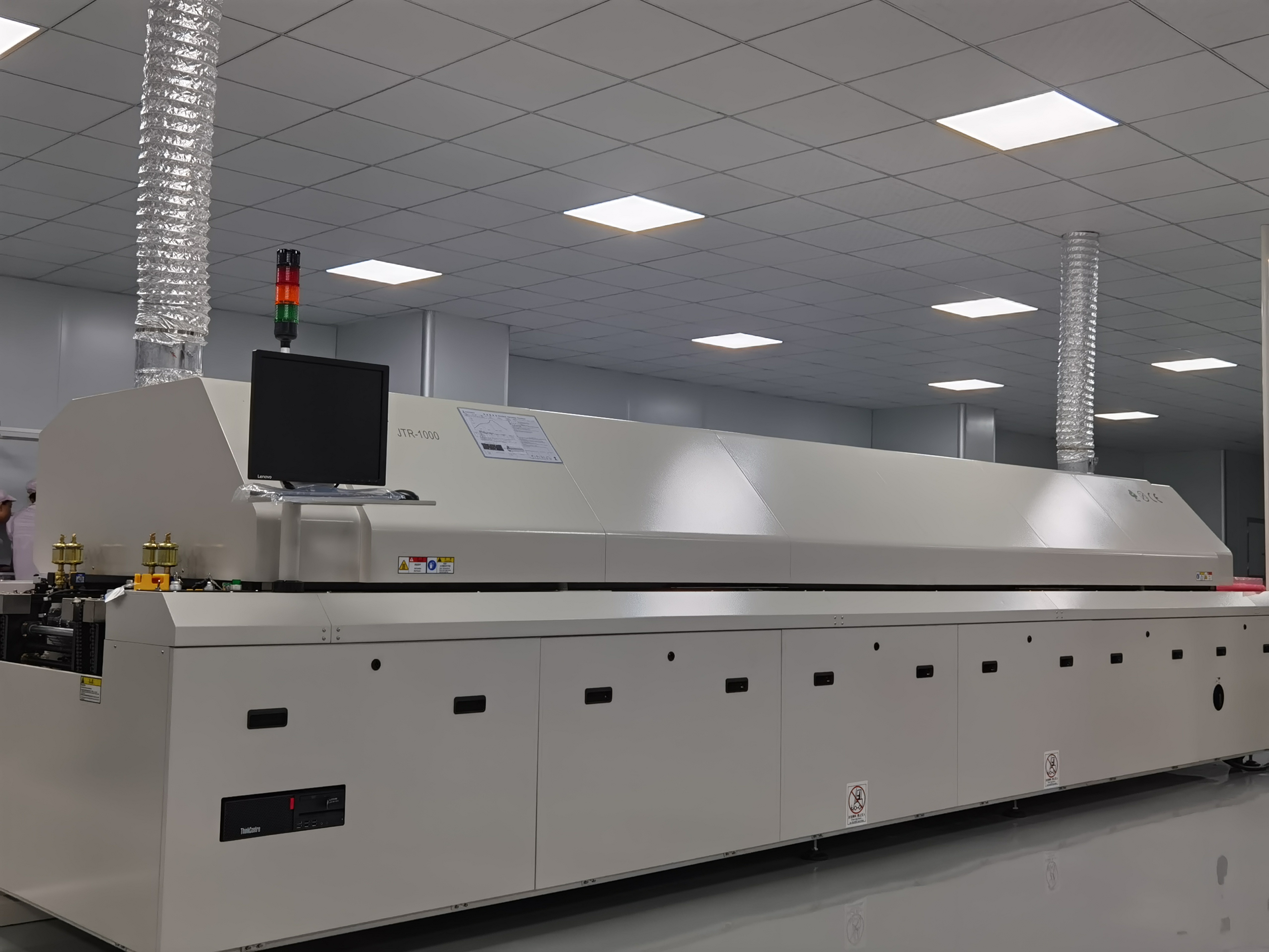
To get good results with wave soldering, you need special tools. The main machine used is a wave soldering machine. It has important parts like solder pots, pumps, and wave nozzles. These parts create the melted solder wave. Preheating zones are also needed. They warm up the PCB to get it ready for soldering. This step helps the flux work and prevents heat damage.
Modern machines often have systems to check temperatures in real time. These systems help you track data and adjust settings for better results. Cleaning the flux system and solder pots daily keeps the machine working well. This also makes the machine last longer.
Tip: Check and maintain your machine often to avoid mistakes and make stronger solder joints.
Materials and Flux Selection
Picking the right materials and flux is very important for wave soldering. Solder alloys should be strong, conduct electricity well, and melt at the right temperature. Common alloys like Sn63Pb37 or lead-free SAC305 work well in many situations.
Flux helps the solder stick properly. Choose flux that matches your solder alloy and PCB surface. For example, HASL surfaces work with most fluxes, but OSP surfaces may need special flux.
Using enough flux stops problems like gaps or solder bridges. Machines that spray flux evenly are best, but if done by hand, you need to be careful.
Key Process Parameters
Good wave soldering depends on controlling key settings. These include conveyor speed, preheat temperature, and solder bath temperature. The conveyor must move at the right speed to match the flux and PCB needs. For example, 1000 mm/min is a good speed to avoid mistakes.
Preheating is important to make the flux work and help solder flow. Temperatures between 105 °C and 145 °C prepare the PCB. Solder temperatures above 220 °C ensure the solder fills all holes. Adjusting time and heat can improve the solder joints.
Parameter | Description |
|---|---|
Conveyor Speed | Matches spray settings for even flux application. |
Preheater Setting | Works with conveyor speed to activate flux properly. |
Temperature | High temperatures above 220 °C make better solder joints. |
Note: Software tools can help you set these parameters for better results.
Best Practices for Component Placement and PCB Design
Optimizing Component Orientation for Wave Soldering
How you place parts on the PCB matters a lot. Align multi-pin SMT components with the solder wave's direction. This stops problems like trailing pins. Smaller parts should go through the wave sideways for even soldering. Big thru-hole connectors work better when placed across the wave.
Don’t put small parts behind big ones. This avoids shadowing, which blocks solder flow and causes defects. If there are surface-mount parts on the back, make sure they don’t block thru-hole pins. Following these tips makes soldering faster and reduces mistakes.
Tip: Check IPC rules for pad shapes to avoid solder issues.
PCB Layout Design to Minimize Defects
Good PCB design helps prevent soldering problems. Keep small parts away from big ones so the solder wave can reach everything. Leave enough space between parts to stop solder bridges. For boards with many layers, preheat them to 100°C–110°C. This helps solder stick better and lowers heat stress.
Think about where you place labels and markings. Resin or ink from labels can mess up solder flow. Designing the board to avoid this keeps soldering smooth.
Guidelines for Solder Mask and Pad Design
The way you design solder masks and pads affects soldering quality. The hole size should be the pin size plus 0.010 inches. This allows good solder flow and avoids incomplete joints. If the hole is too big, soldering gets harder. Keeping the right size is key.
The thickness of the pin coating also matters. A 0.005µm layer can keep pins usable for over a year. Adding copper to brass pins stops damage from zinc exposure. Proper plating keeps soldering reliable and prevents quick wear.
Note: Follow these design tips to reduce errors and get strong solder joints.
Common Defects in Wave Soldering and Prevention Strategies
Identifying Common Defects (e.g., solder bridging, insufficient solder)
Problems can happen in wave soldering if settings are wrong. Two common problems are solder bridging and not enough solder. Solder bridging happens when too much solder connects nearby pins or pads. This creates unwanted electrical links. Not enough solder means the pad or pin isn’t fully covered. This can cause weak joints or open circuits.
You can spot these problems with visual checks or machines. For example, solder bridging drops below 0.30% when solder is hotter than 230°C. Keeping solder at 235°C and conveyor speed at 1000 mm/min helps reduce bridging. Preheating the PCB to 105°C–145°C makes flux work better. This lowers voids and improves solder quality.
Process Optimization to Prevent Defects
Fixing wave soldering settings can lower defects. Adjust conveyor speed, solder heat, and preheating for better results. For example, one smartwatch company cut defects by 70%. They used special materials like Durostone and Ricocel. These materials kept temperatures steady within ±2°C on 50mm² PCBs. They also lasted 18 months, unlike older materials that lasted only 6 months.
Controlling wave height also helps prevent problems. A steady solder wave gives even coverage. This lowers the chance of solder bridging or missing solder. Cleaning solder pots and flux systems often also reduces defects.
Role of Preheating and Flux in Defect Prevention
Preheating and flux are key for good wave soldering. Preheating gets the PCB ready and lowers heat stress. It also helps solder flow better. Keeping preheat between 105°C and 145°C makes flux work well. This reduces voids and improves solder joints.
Flux helps solder stick to the PCB. Too little flux makes solder not stick well, causing bad joints. Using the right amount of flux keeps soldering smooth and stops defects. But too much flux can leave residue, which causes problems.
Tip: Watch flux levels and preheat temperatures to avoid soldering mistakes.
Quality Control Measures and Standards
Inspection Techniques for Wave Soldered Assemblies
Checking solder quality is very important in wave soldering. Special methods help find problems and check solderability. One way is to study how solder sticks to surfaces. This method looks at things like how fast solder starts sticking, the strongest sticking point, and how long it takes. These details show how good the soldering is.
Parameter | Description |
|---|---|
Initial Dip | Force goes down when the PCB is dipped in solder. |
Wetting Initiation | Force rises as solder starts sticking after flux works. |
Zero Crossing | The point where solder begins to stick to the surface. |
Wetting Rate | How fast solder sticks; faster means better soldering. |
Maximum Wetting Force | The highest force, showing the best soldering condition. |
Wetting Time | Time to reach a set part of the highest force. |
Machines like AOI and X-ray systems also find problems like solder bridges or missing solder. These tools make sure the soldering is done right and reduce human mistakes.
Tip: Regular checks help avoid problems and save time fixing errors.
Industry Standards for Wave Soldering Quality
Following rules ensures good wave soldering results. Products are grouped into three types: general, service, and high-performance. Each type has its own rules for cleaning, heating, and fixing mistakes.
Class | Description |
|---|---|
1 | Everyday electronic items |
2 | Electronics for services |
3 | High-quality electronics |
Requirement | Description |
|---|---|
Cleanliness | Keep tools and materials free from dirt. |
Heating/Cooling Rates | Follow maker’s rules to protect parts. |
Wire Strands | Wires must stay intact; solder should cover tinned areas. |
Inspections | Check before adding coatings or stacking boards. |
Defects | Fix or remove bad parts as customers want. |
Visual Inspection | Use AOI and X-ray tools to check quality. |
Design Compliance | Leads and conductors must fit exposed metal areas. |
These rules help lower mistakes and meet customer needs.
Automated Quality Control Systems by LTPCBA
LTPCBA uses smart machines to keep wave soldering quality high. Tools like AOI and X-ray find problems quickly. Real-time monitors check things like heat and conveyor speed. This keeps production steady and reliable.
LTPCBA also follows global rules like ISO and UL. These show their promise to deliver top-quality work. With advanced tools and skilled workers, LTPCBA makes strong PCBs that meet industry needs.
Note: Picking LTPCBA means getting great quality and smooth production.
Why Pick LTPCBA for Wave Soldering Services
Modern Wave Soldering Machines
LTPCBA uses advanced machines for great wave soldering results. These tools make strong connections and reliable solder joints. They also control flux better for smoother soldering. Nitrogen systems stop oxidation, improving solder quality. Real-time checks keep the process steady and reduce mistakes.
Quality Feature | Wave Soldering | Other Methods |
|---|---|---|
Strong Connections | Yes | Sometimes |
Reliable Solder Joints | High | Lower |
Stops Oxidation | Yes (with nitrogen) | No |
Flux Control | Optimized | Less precise |
Process Control | High | Variable |
These machines work 30% faster than older ones. Inspections take only seven seconds and find 99% of problems. LTPCBA’s machines are fast and accurate, giving you great results.
Focus on Quality Checks
LTPCBA ensures quality at every step of wave soldering. Tests like edge dip and wetting balance check solder strength and reliability. They follow strict rules like MIL-STD-883, ensuring 95% solder coverage with few flaws.
Test Type | What It Checks | Passing Score |
|---|---|---|
Edge Dip Test | Checks how well solder sticks. | At least 95% wetting |
Wave Solder Test | Looks at soldering conditions. | No visible defects |
Wetting Balance Test | Measures solderability. | At least 95% wetting |
MIL-STD-883 Method 2003 | Full solderability check. | 95% coverage, under 5% flaws |
Automated tools like AOI and X-ray inspections find problems quickly. These tools ensure high-quality soldering every time. With LTPCBA, you get dependable results backed by proven methods.
Skilled in SMT Assembly and PCB Making
LTPCBA is skilled in SMT assembly and PCB production. Certifications like IPC-A-610 and AS9100 show their focus on quality. Advanced tests, like optical and X-ray checks, find issues in multi-layer PCBs. Burn-in tests ensure parts last under stress.
Certification | Purpose |
|---|---|
IPC-A-610 | Ensures quality in PCB assembly. |
AS9100 | Guarantees top quality for aerospace projects. |
UL Certification | Ensures safety and compliance with electrical standards. |
Test Type | Description |
|---|---|
Optical Inspection | Finds visible PCB problems. |
X-Ray Inspection | Spots hidden issues in layered PCBs. |
Electrical Testing | Checks if circuits work correctly. |
Burn-In Testing | Tests long-term reliability under stress. |
You also get 24-hour tech support and quick help when needed. LTPCBA tracks and fixes complaints to keep customers happy. Their skills ensure top-quality PCBs made just for you.
To do wave soldering well, focus on key details and tips. Following these steps can cut 96% of extra fixes. This ensures strong solder joints the first time. LTPCBA’s modern tools and focus on quality make them a great choice for perfect PCB assemblies.
FAQ
1. What is the best temperature for wave soldering?
Keep the solder bath hotter than 220°C. Preheat the PCB to 105°C–145°C. This helps the flux work and makes solder flow better.
2. How do you stop solder bridging in wave soldering?
Change the conveyor speed and wave height as needed. Use the right amount of flux and preheat the PCB. This improves solder flow and stops bridging.
3. Why is flux needed in wave soldering?
Flux cleans off oxidation and helps solder stick well. Using flux correctly makes strong joints and avoids problems like gaps or weak solder.
See Also
Essential Guidelines for Wave Soldering in DIP Assembly
Common Methods and Workflow for SMT Assembly Processes
Top Strategies for Optimizing SMT Lines in PCBA
Meeting SMT Assembly Standards for Automotive Manufacturing
Designing PCBs for Optimal SMT Processing and Manufacturability