Soldering Quality Factors: Factors Affecting SMT Wave Soldering Quality and Common Defects with Preventive Measures

You need to know about soldering quality factors to get good results in SMT and wave soldering. Trained workers, machine checks, and strong rules help stop problems in printing, solder, and pcb assembly. LTPCBA uses new technology and quick help to give high wave quality and steady printing each time.
Key Takeaways
Pick the correct materials and plan your PCB well. This helps stop most soldering problems. It also makes sure the joints are strong and last long.
Watch solder paste printing, temperature, and machine settings closely. This stops problems like not enough solder, bridging, and cold joints.
Check and fix equipment often. Use machines like AOI and X-ray to find problems early. This keeps soldering quality high.
Soldering Quality Factors
Materials and Solder Alloys
You must use the right materials for good soldering. The type of solder alloy and solder paste matters a lot. Most companies now use lead-free solder because of REACH rules. Lead-free solder melts at a higher temperature than leaded solder. You need to watch the temperature closely so parts or the PCB do not get damaged. Using lead-free solder can cost more and slow down supply. So, you should check your materials and process often.
Statistic / Factor | Description |
|---|---|
Most problems come from PCB design, like picking the wrong material, bad layout, or pad design. | |
Key materials affecting soldering quality | Components, solder paste, and PCB pads are very important. If these have problems, it is hard or impossible to fix. |
Reflow curve settings depend on | The melting point of solder paste, how much heat parts can take, the PCB’s size and thickness, and the oven’s features. |
The strength of solder joints depends on the solder alloy you use. For example, SAC-based solders with Bi, Sb, and Ni work better than old SnPb alloys. Good solder paste and storage, like vacuum packing and dry cabinets, stop oxidation and dirt. These steps help keep your soldering steady and lower the chance of defects.
PCB and Pad Design
How you design the PCB and pads is very important for soldering. HP says 80% of problems come from design, and 40% to 60% are from the substrate. You need to pick the right substrate and make pads that solder well. The size, shape, and finish of pads change how solder flows and sticks.
Parameter | Copper Pads (Hot Plate) | Copper Pads (Hot Air) | Epoxy Pads (Hot Plate) | Epoxy Pads (Hot Air) |
|---|---|---|---|---|
Solder Joint Resistance (Ω) | 0.17 | 0.18 | 0.22 | 0.27 |
Peak Detachment Force (N) | 87.67 | 71.40 | 39.32 | 39.21 |
This table shows copper pads make stronger solder joints than epoxy pads. If you use other pad materials, you may need to make pads bigger to keep them strong. Good PCB and pad design help stop common wave soldering problems and make boards more reliable.
SMT Process Parameters
You must control many steps to get good SMT and wave soldering. The most important things are solder paste amount, printing accuracy, and the temperature curve. Studies say up to half of soldering problems start with solder paste printing. Checking solder paste amount and printing early saves time and money.
Solder paste should be over 50% for passive parts and over 40% for leaded parts.
Printing accuracy and stencil design help paste go on pads well.
The temperature curve must fit the solder paste and parts to stop cold joints or overheating.
Tip: Use solder paste inspection (SPI) to check paste amount, height, and placement after printing. This helps you find problems early.
You should also watch wave height, conveyor speed, and solder wave temperature. Keeping these steady helps stop bridging, not enough solder, or bad wetting. Automated optical inspection (AOI) and looking at boards after soldering help you find and fix problems before the next step.
Equipment and Environment
Your machines and work area affect soldering quality a lot. You need to clean and check your wave soldering machine and reflow ovens often. Cleaning, checking, and setting the temperature should follow a schedule:
Maintenance Task | Recommended Frequency |
|---|---|
Cleaning | Daily |
Inspection | Weekly |
Replacement of worn components | Monthly |
Quarterly |
Good maintenance stops breakdowns and keeps soldering steady. You also need to control the air and temperature in your work area. Changes in humidity and temperature can hurt soldering. Studies show that keeping the environment steady helps lower defects during printing and soldering.
Note: Use advanced systems with nitrogen and real-time temperature checks to make soldering better and stop oxidation during wave soldering.
LTPCBA Quality Assurance
LTPCBA pays close attention to every part of soldering. The company uses new technology and machines to control solder paste, printing, and wave soldering. LTPCBA follows world standards like ISO, IATF, and UL, and keeps records for every test and check.
Metric/Process Aspect | Description/Value | Impact on Quality and Reliability |
|---|---|---|
First Pass Yield | Less rework and faster delivery | |
Pick-and-Place Accuracy | 99.95% | Parts are placed right, so there are fewer problems |
AOI and ICT | Used at every step | Problems are found early |
Solder Paste Application | Controlled by stencil and thickness | Over 70% of soldering success depends on this |
Reflow Soldering | Precise temperature control | Makes solder joints strong and steady |
Final Testing | Functional, electrical, durability, strength tests | Checks boards before shipping |
Statistical Process Control | Data-driven quality control | Keeps quality steady and helps improve processes |
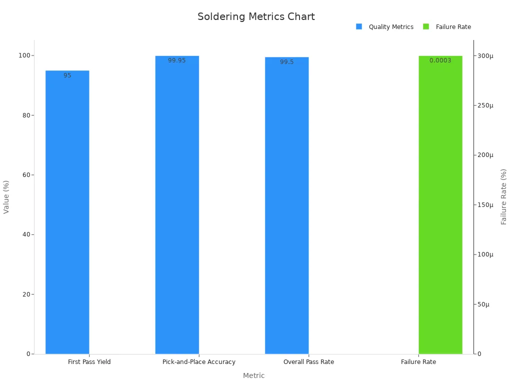
LTPCBA gives fast help and 24-hour support to fix problems quickly. Their AOI and X-ray checks find issues early, and strict controls make sure every PCBA is high quality. With a 99.5% pass rate and very few failures, LTPCBA helps you trust your SMT and wave soldering projects.
Wave Soldering Defects
Wave soldering can introduce many defects if you do not control the process carefully. Studies show that wave soldering can cause up to 50% of all defects in PCB assembly. You need to know the main types of soldering defects, their causes, and how to prevent them. Good process control and inspection help you keep your SMT and wave soldering quality high.
Insufficient Solder
Insufficient solder happens when you do not get enough solder on the joint. You might see exposed metal, thin solder layers, or weak connections. This defect often comes from low solder wave height, poor solder paste printing, or not enough flux. Sometimes, the solder does not wet the pad or lead because of contamination or oxidation.
Measurement Criterion | Acceptance Threshold | Rejection Indicators |
|---|---|---|
Visual Coverage Percentage | Coverage < threshold, exposed base metal | |
Wetting Balance Test | High wetting force | Low force, slow wetting, dewetting |
Visual Inspection (10x-20x) | Smooth, full cover | Pinholes, voids, non-wetting, dewetting |
To prevent insufficient solder, you should:
Check solder paste amount and printing accuracy.
Keep the solder wave height steady.
Use clean, fresh solder paste and flux.
Inspect joints with AOI and magnification.
LTPCBA uses AOI and strict process checks to catch insufficient solder early. Their systems measure solder coverage and wetting, so you get strong, reliable solder joints.
Solder Bridging
Solder bridging means solder connects two pads or leads that should stay separate. This defect can cause shorts and make the PCB fail. Solder bridging often comes from too much solder paste, high solder wave temperature, or poor pad design. If the conveyor speed is too slow, the solder can flow and bridge gaps.
Parameter | Condition/Value | Effect on Defect Frequency |
|---|---|---|
Peak solder temperature | Bridging drops below 0.30% | |
Conveyor speed | 1000 mm/min | Reduces bridging and defects |
To stop solder bridging, you should:
Adjust solder paste printing and stencil design.
Set the right solder wave temperature and conveyor speed.
Use AOI to spot bridges after soldering.
LTPCBA’s AOI systems find even tiny bridges. Their process control keeps solder wave and printing steady, so you avoid most bridging defects.
Voids and Blowholes
Voids and blowholes are empty spaces or bubbles inside the solder joint. These defects weaken the joint and can cause failures over time. Voids often come from trapped gas, moisture, or poor flux activation. If you do not preheat the PCB enough, flux cannot clean the surfaces, and gas stays inside the solder.
Defect Type | Metric (Measured) | IPC Standard | Typical Value (Observed) |
|---|---|---|---|
Voids/Cavities | Fill % | IPC-A-610 | |
Void Size | % of joint height | IPC-A-610 | 67.9%, 53.3% |
To reduce voids and blowholes:
Control solder paste moisture and storage.
Use X-ray and AOI to inspect for hidden voids.
LTPCBA uses X-ray and AOI to check for voids. Their process keeps solder paste and wave conditions steady, so you get fewer voids and better soldering quality.
Solder Balls and Flags
Solder balls are small, round bits of solder stuck to the PCB. Solder flags are odd shapes or tails of solder sticking out from joints. These defects can cause shorts, poor looks, and lower reliability. Solder balls form when you use too much solder paste, have moisture in the paste, or set the wrong reflow or wave temperature. Poor stencil design and dirty boards also increase solder balls.
Solder balls can cause a PCB to fail if you see more than five balls (≤0.13mm) in a 600 mm² area.
AOI helps you find solder balls and flags quickly.
To prevent solder balls and flags:
Control solder paste printing and stencil design.
Keep the PCB and solder paste dry and clean.
Set the right wave and reflow temperatures.
Use AOI for fast inspection.
LTPCBA uses AOI and strict printing controls to stop solder balls and flags. Their process checks and equipment keep solder paste and wave settings just right.
Cold and Excess Solder
Cold solder joints look dull, rough, or cracked. They happen when the solder does not melt or wet the pad well. You might see high resistance or open circuits. Cold solder joints come from low solder wave temperature, fast conveyor speed, or moving the PCB before the solder cools.
Excess solder means too much solder on the joint. This can cause shorts, bridging, or hard-to-test boards. Excess solder comes from too much solder paste, slow conveyor speed, or too long in the solder wave.
Cold solder joints show up as dull, irregular shapes with cracks.
Excess solder looks like big blobs or bridges.
To avoid cold and excess solder:
Set the right solder wave temperature and conveyor speed.
Control solder paste printing and amount.
Do not disturb the PCB while solder cools.
Use AOI and X-ray to check joints.
LTPCBA uses real-time monitoring and AOI to catch cold and excess solder. Their process keeps soldering steady, so you get strong, clean joints.
Preventive Measures in SMT
You can stop most soldering defects by using good process control and inspection. Over half of SMT soldering defects start with poor solder paste printing. You should:
Use real-time monitoring and automated systems to spot soldering problems fast.
Keep equipment clean and calibrated for steady performance.
Adjust solder paste printing by changing stencil design and printer settings.
Train operators and improve skills often.
Apply Design for Manufacturability (DFM) to make PCBs easier to solder.
Use feedback and Statistical Process Control (SPC) to track trends and fix issues.
Tip: AOI and 3D AOI systems help you find tiny soldering defects that people miss. These systems work fast and do not get tired, so you catch more problems early.
LTPCBA uses AOI, X-ray, and SPC to keep soldering quality high. Their systems collect data and adjust the process in real time. This helps you get fewer defects, better yield, and more reliable PCB assemblies.
You can get better soldering by using good materials and smart PCB design. It is important to control the wave process well. Checking with AOI, X-ray, and ICT helps find problems early. LTPCBA’s quality systems make wave soldering strong and reliable. Keep making your process better for the best soldering results.
FAQ
What is the most common cause of soldering defects?
Most defects come from poor solder paste printing or bad PCB design. You should check these steps first if you see many problems.
How does LTPCBA help reduce wave soldering defects?
LTPCBA uses AOI, X-ray, and strict process checks. You get early defect detection and strong quality control for every PCB assembly.
Can you prevent solder bridging during SMT assembly?
Yes. You can use the right stencil design, control solder paste amount, and set proper machine speeds.
Tip: AOI systems help you catch bridges quickly.
See Also
Typical Reflow Soldering Flaws In SMT And How To Avoid
Frequent SMT PCB Assembly Issues And Effective Prevention Tips
Reasons Components Detach During Wave Soldering In SMT Production
Essential Technical Tips For Wave Soldering In SMT Assembly
Problems From Uneven Temperature In SMT Reflow Soldering Process