SMT Soldering techniques for 0201 and 01005 size components
You need very careful SMT soldering techniques for 0201 and 01005 micro chip components. Working with these SMD parts on a PCB is a real test of your soldering skills. Problems like uneven solder, graping, and tombstoning can happen because you must be very accurate at this size. Special tools help you put tiny parts in place and control the solder on crowded PCB layouts. Using proper SMT soldering techniques to apply the right amount of solder on each PCB pad helps prevent mistakes. Solder joint strength depends on how well you control the process. You must watch out for heat and pick the right solder for every micro chip component on your PCB. Solder bridges and shorts can happen if you are not careful with PCB accuracy. The best SMT soldering techniques keep your solder joints strong and your surface mount devices working well on every PCB.
Key Takeaways
Use special tools like fine-tip soldering irons, tweezers, and microscopes. These help you work with small 0201 and 01005 parts. They let you avoid problems like tombstoning and solder bridges.
Pick the right solder paste and stencil design. Watch the reflow oven temperature and profile. Make sure pad sizes and spacing are correct. This helps make strong and reliable solder joints.
Check solder paste and part placement often with SPI and AOI systems. Keep your tools clean. Control the room’s temperature and humidity. This lowers defects and helps you get good results the first time.
SMT Soldering Techniques
Hand Soldering
Hand soldering 0201 and 01005 SMD micro chip components is hard. These parts are tiny, so small mistakes can cause tombstone defects or solder bridges on your PCB. You need steady hands and good tools to do this well.
Pick a fine-tip soldering iron with a tip as small as 0.5mm. Set the temperature 20-30°C higher than the solder’s melting point. This stops you from overheating the SMD or the PCB.
Fine-tip tweezers help you pick up and place micro chip components accurately. Heated tweezers let you solder both ends of a two-terminal SMD at once.
Put a little solder paste on the PCB pad. Hold the SMD in place, then use your iron or a hot air pencil to reflow the joint. This tack and reflow method keeps the part steady and lined up.
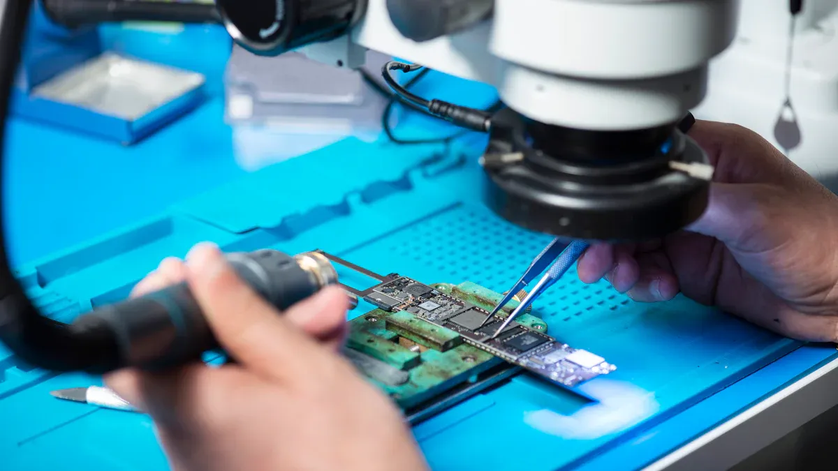
Use a microscope with 20x to 40x magnification. This helps you see the soldering process and check for tombstone defects or bad solder joints.
Always use flux. It helps the solder flow and stick to the pad and SMD. Pick a flux that works with your soldering process and SMD type.
Tip: Practice matters a lot. Industry training courses spend most time on hands-on soldering and fixing these tiny SMDs. The more you practice, the better your solder joints will get.
Reflow Soldering
Reflow soldering is the main way to put 0201 and 01005 SMDs on a PCB. You print solder paste on the pads, place the SMDs, and heat the board in a reflow oven. The solder melts and makes strong joints.
Parameter | Recommended Value / Observation |
|---|---|
Stencil Thickness | |
Solder Paste Type | Type 4 (Type 5 for better wetting, but higher cost) |
Pad Dimensions (Capacitors) | 210 µm × 220 µm, 160 µm separation |
Pad Dimensions (Resistors) | 190 µm × 220 µm, 160 µm separation |
Minimum Component Spacing | 100 µm |
Mounting Force | 1 N (low force to avoid cracks) |
Squeegee Speed | 20–40 mm/sec |
Lead-free Solder Effects | Higher risk of bridging and tombstone due to lower wettability |
Board Area Savings | 01005 pads save about 50% board area compared to 0201 |
Use a thin stencil and Type 4 solder paste for best results. Type 5 paste wets even better but costs more. Keep mounting force low so you do not break the SMDs. Make sure pad size and spacing fit the SMD size to stop solder bridges and tombstone defects.
Reflow ovens use hot air to heat the PCB. Some companies use nitrogen to help solder wetting and stop oxidation. But nitrogen costs more and makes things harder. Most times, you get better results by controlling oven temperature and stencil printing.
Change the preheat slope rate and stencil hole size to lower tombstone defects.
Focus on good pad design and solder mask quality. Shiny solder joints are not always good. Look for full wetting and smooth fillets.
Control room temperature and humidity. Thin solder paste dries fast, which can hurt soldering quality.
Note: Tombstone defects happen when one end of the SMD lifts up during reflow. This is common with 0201 and 01005 SMDs if the solder melts unevenly or the pad design is wrong.
Equipment and Tools
You need special equipment and tools to work with these tiny SMDs. The right setup makes your SMT soldering techniques better and lowers defects.
Aspect | Recommendation |
|---|---|
Soldering Iron Power | |
Tip Size | 0.5mm fine tip |
Temperature Control | Use a temperature-controlled iron |
Additional Tools | Fine-tip tweezers, 20x-40x microscope, solder paste, stencils, jigs, helping hands |
Use advanced pick-and-place machines for placing components. These machines use servo motors, air nozzles, and vision systems to place SMDs very accurately. They stop tombstone and bridging defects by using light force and special nozzles.
Keep your nozzles and feeders clean. Even a little dust can cause bad placement or poor pickup. Clean them often.
Use three local fiducials on your PCB. This helps the machine adjust for board changes and makes placement more accurate.
Check your solder joints with a microscope. Use stereo vision for depth and a ring light for clear viewing. Magnification between 20x and 40x works best for 0201 and 01005 SMDs.

Always use ESD-safe tools and work in an ESD-protected area. Store SMDs in anti-static packaging and label them clearly.
Keep solder paste in a fridge at 2-10°C. Let it warm up before use to stop condensation. This keeps the flux working and stops soldering problems.
Control the room’s temperature and humidity. This helps keep the solder paste and PCB ready for soldering.
Tip: The type and amount of flux, and how you use it, affect solder joint strength. For small SMDs, flux can dry up fast, so slow down the preheat ramp and help wetting.
You can master SMT soldering techniques for 0201 and 01005 SMDs by using the right tools, careful process control, and regular checks. This helps you stop tombstone defects, solder bridges, and weak solder joints on your PCB.
Design and Process Essentials

Pad and Stencil Design
You have to follow strict rules for solder pads when working with 0201 and 01005 components. The size and space of each pad on your pcb are very important. They help stop tombstone defects from happening. If the pads are too far apart, the parts can fall over during reflow. Pads that are not the same size or are spaced unevenly cause problems. This makes the solder pull harder on one side. That can lift up one end and cause a tombstone defect.
To stop tombstone, keep the pad space between 0.1 mm and 0.3 mm for 0201 parts. Use pads that are rectangles and all the same size. This helps keep the part steady and the solder even. Wider pads give more area for the solder to hold the part down. Always make sure the pad size, shape, and space match the part size. If you turn parts that get tombstone 90° to the air flow, both ends heat at once. This lowers the chance of tombstone.
Stencil design is just as important as pad design. You need to control how much solder paste you print. Use a high area ratio, above 0.66, for good paste release. Thin stencils, down to 62 µm, help keep the area ratio high. If you cannot use a thinner stencil, you can make the opening wider. But you must be careful not to cause solder bridges. Special shapes, like trapezoids or rounded corners, help the paste come out better. Step stencils let you use more paste for big parts and less for small ones. Nano-coatings on stencils also help the paste come out, which is good for crowded boards.
Tip: Clean your stencil often. Dried solder paste in small holes causes bad printing and more tombstone defects.
Solder Paste Selection
Picking the right solder paste is very important for good soldering and stopping tombstone. For 0201 parts, use Type 4 solder paste. For 01005, Type 5 is best, but you can use Type 4 if you have trouble printing. The table below shows what type to use:
Component Size | Recommended Solder Paste Type |
|---|---|
0402 | Type 3 |
0201 | Type 4 |
01005 |
Type 4 solder paste has powder about 25 microns wide. This helps the paste come out of the stencil holes and print well. For the smallest 01005 parts, Type 5 or even Type 6 pastes have smaller powder. This helps with printing tiny spots. Smaller powder means more surface area, so the flux in the paste has to work harder. You might need to change the flux to get the best results.
How the solder paste flows is important. Good flow means the paste comes out of the stencil without getting stuck. Use a stencil that is 3 or 4 mils thick, depending on your pad design. Using nitrogen in the reflow oven can help stop tombstone, especially for small parts. Keep nitrogen between 500 and 1000 PPM for the best results.
Note: Make sure the solder paste is the same amount on each pad. If not, you can get tombstone, solder balls, or bridges.
Reflow Profile
You need to set the right reflow profile to stop tombstone and get strong solder joints. Use a ramp-to-peak or ramp-to-spike profile. Heat the board at a rate of 1-2°C per second. This helps both ends of the part heat at the same time. Do not soak for too long, or the solder paste will lose its stickiness and the flux will run out.
Set the highest reflow temperature about 20-30°C above the solder melting point. For lead-free solder, aim for 235–245°C at the peak. Keep the ramp rate under 1.5°C/sec near the hottest part. This helps stop tombstone. The time above liquid should be about 60 seconds. Cool the board at 2-4°C per second to stop thermal shock.
Parameter | Lead-Free Solder (Sn-Ag-Cu) | Lead-Containing Solder |
|---|---|---|
Peak Temperature | 235–245°C | 210–220°C |
Ramp Rate | ≤3°C/sec | ≤3°C/sec |
Dwell Time Above Liquidus | 30–60 seconds | 40–90 seconds |
Make sure the whole pcb heats evenly. Try to keep the temperature difference below 10°C. Change the top and bottom heater settings to balance the heat. This is important if your pcb has thick and thin areas. Ovens with many zones help you control the temperature better.
Callout: If you see tombstone, check your reflow profile and make sure both pads heat the same.
Defect Prevention
You can stop most defects by following strict rules for design, solder paste printing, and process control. Tombstone, solder balls, bridges, and wicking are common with 0201 and 01005 parts. These problems often come from heat differences, bad solder paste amounts, and placement mistakes.
Follow these steps to lower defects:
Use solder paste inspection (SPI) to check the amount, height, and area of each paste spot. This helps you find problems that cause tombstone and bridges.
Check the part size and make sure the paste is even on all pads. For 0201, keep the paste amount within 25% between pads.
Use advanced SPI tools, like special software and jet dispensers, to fix low paste spots without printing again.
Make your stencil design and printing settings better to keep the paste printing the same every time.
Study your process and fix root causes, like pcb bending or stencil problems.
Manual checking does not work well for these tiny parts. Use Automatic Optical Inspection (AOI) systems with high-res cameras to check for placement and soldering problems. AOI can find over 98% of visible problems. For hidden problems, use X-ray inspection.
Cleaning is also important. Clean your stencil right away to stop paste from drying, especially for 01005 and 0201 holes. Use semi or automatic cleaning machines to cut down on mistakes. For no-clean paste, clean every 3 pcbs. For normal paste, clean every 5-10 pcbs. Change your cleaning schedule based on what you see in inspections and what your process needs.
Tip: Good control of room temperature (67-69°F) and humidity (40-50% RH) lets you print more boards before cleaning. Bad control means you have to clean more and get more defects.
By following these rules, you make soldering better, lower tombstone defects, and get more good boards from your process. Always focus on placing parts right, printing the same amount of solder paste, and keeping your process tight for the best results.
You can make SMT assembly work well for 0201 and 01005 components if you use the right tools, plan carefully, and check your work a lot.
When you use SPI, AOI, and ICT, most boards pass the first test. The first-pass yield can be higher than 99.8%.
Making lots of boards at once needs special machines and more checks. This costs more money, but it stops big problems and helps your boards last longer.
FAQ
What is the best way to avoid tombstone defects with 0201 and 01005 parts?
Use pads that are the same size. Make sure you use the right amount of solder paste. Set the reflow profile so both sides heat the same. Place the parts carefully and check your work. This helps stop tombstone defects.
Can you hand solder 01005 components reliably?
You can hand solder 01005 parts if you use a fine-tip iron. Good tweezers and a microscope help a lot. You need steady hands and lots of practice.
Which solder paste type works best for these tiny components?
Component Size | Solder Paste Type |
|---|---|
0201 | Type 4 |
01005 | Type 5 |
Type 4 or 5 solder paste prints better. You get fewer mistakes and better results.
See Also
Step-By-Step Guide To Reflow Soldering Through-Hole Parts Post-SMT
Essential Process Criteria For Reflow Soldering During SMT Assembly
Comprehensive Technical Instructions For Wave Soldering In SMT
Understanding Solder Paste Types And Component Variations In SMT
Top SMT Assembly Practices To Ensure Superior Electronics Quality