How to Assemble SMT Circuit Boards: A Complete Stepwise Approach
SMT circuit board assembly utilizes advanced surface mount technology to place and solder components directly onto the PCBA. This precise, step-by-step smt circuit board assembly process is designed to prevent common issues such as solder bridges, misalignment, and warpage, all of which can impact the performance and reliability of your board.
Metric | Value |
|---|---|
Overall PCBA Market Size (2024) | |
Projected PCBA Market Size (2033) | USD 50.3 Billion |
SMT Segment CAGR (through 2033) | Over 7.5% |
To ensure every smt circuit board assembly meets the highest standards, you need quality, accuracy, and reliability. LTPCBA delivers trusted smt circuit board assembly services, leveraging intelligent systems and rigorous quality control to guarantee exceptional results.
Key Takeaways
Checking and getting materials, workspace, and tools ready helps stop common SMT assembly mistakes and gives good results. - Using exact machines for putting on solder paste and placing parts, along with careful checks like AOI, helps find mistakes early and makes the assembly better. - Cleaning, testing, and packing the boards the right way keeps them safe from harm and makes sure they work well for a long time.
Material Inspection
PCB Check
You begin by looking at each pcb closely. Careful checking helps you find problems early. This stops bigger issues later in the process. Some common pcb problems are dendrite growth, plating voids, solder dewetting, cold solder joints, solder bridging, sunken joints, tombstoning, shadowing, acid traps, slivers, and delamination.
You can lower these problems by following good design rules. Use high-quality parts and good soldering methods.
Automated Optical Inspection (AOI) and In-Circuit Testing (ICT) help you spot hidden issues in the printed circuit board assembly.
Here is a table that lists what to check during material inspection:
Material Type | Inspection Focus | Key Inspection Items / Criteria |
|---|---|---|
PCB Bare Board | Size and Appearance | Aspect ratio, spacing, tolerance, PCB edge size, layer defects (opens, shorts, scrapes, line width) |
Warpage | Measure warpage by pressing corners and checking distance to table surface | |
Solderability | Pad and hole inspection using dip tests and solder ball test | |
Internal Defects | Microsection analysis for copper thickness, layer alignment, lamination defects |
Component Verification
You must check every part before you start the smt pcb assembly process. Look at the model, specs, and electrical values to match your order. Make sure each part can be soldered and works right by testing it.
Industry standards like IPC-A-610, IPC J-STD-001, and ANSI/ESD S20.20 help you do quality checks. These rules help keep the smt pcb assembly process safe and reliable.
Storage Tips
Storing parts the right way keeps them safe for smt pcb assembly.
Ground yourself before you touch any parts.
Do not touch leads or sensitive spots.
Store parts in ESD-protected boxes.
Use static shielding bags when moving parts.
Check and change old ESD materials.
Keep your work area ESD-safe with the right floors and benches.
Tip: Storing parts well and checking them carefully helps you avoid expensive mistakes in smt pcb assembly.
Preparation
Starting well is important for smt pcb assembly. Getting ready before you begin helps stop mistakes. It also makes the work faster. LTPCBA uses smart machines and quick help to get good results for every pcba job.
Work Area Setup
Your workspace must be clean and safe for smt assembly.
Keep the room between 15°C and 35°C. Humidity should be 45% to 70%.
Use anti-static mats and grounded chairs. Make sure the lights are bright enough (800–1200 LUX).
Do not let dust or bad gases in the area.
Teach everyone to follow safety rules and use tools the right way.
Tip: Good power and air flow help your smt pcb assembly stay safe and smooth.
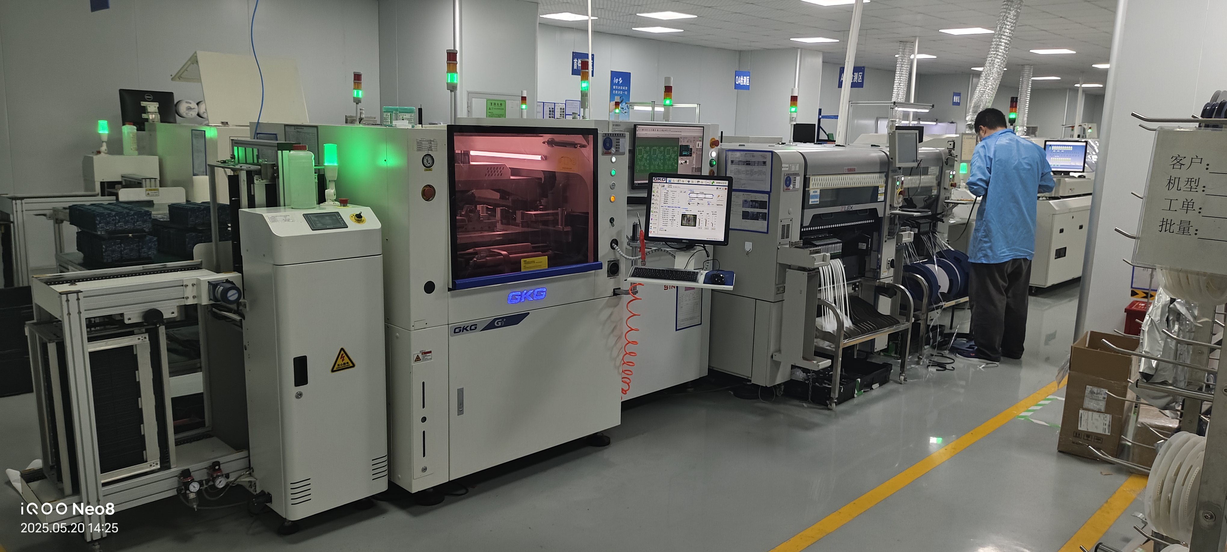
Equipment Readiness
Check all machines and tools before you start. LTPCBA uses fast SMT lines, Yamaha YSM20R machines, and ovens with nitrogen. These tools help put parts on quickly and in the right place. AOI and X-ray machines find problems early. This saves time and stops extra work. Fast testing and building help you finish pcba jobs on time.
Equipment | Benefit for SMT Assembly |
|---|---|
High-speed SMT lines | Fast, accurate component placement |
AOI & X-ray inspection | Quick defect detection |
Nitrogen reflow ovens | Consistent soldering quality |
File and Program Review
Look at all files and programs before you start smt pcb assembly.
Check Gerber files for the right layers and trace sizes.
Make sure the BOM matches all parts and footprints.
See if pick-and-place files have the right spots and directions.
Look at stencil and netlist files for solder paste and checks.
Add test points and clear silkscreen text for easy checking.
Plan how to group boards and do not score too close to parts.
Checking everything first helps you avoid waiting and keeps smt pcb assembly going well from start to finish.
Solder Paste
The smt pcb assembly process needs careful solder paste use. This step helps make strong electrical connections. It also helps the assembly work well. You must pick the right solder paste for your pcb. The table below shows some common types and their good points:
Solder Paste Type | Composition / Characteristics | Advantages | Typical Use Cases / Examples |
|---|---|---|---|
Lead-Free Solder Paste | SAC305 (96.5% Sn, 3% Ag, 0.5% Cu) | Environmentally friendly, strong joints, RoHS-compliant | Consumer electronics, medical, automotive, aerospace |
No-Clean Solder Paste | Minimal residue after reflow | No cleaning needed, saves time and cost | High-volume electronics, IoT devices |
Water-Soluble Solder Paste | Organic acid flux, cleans with water | Easy cleaning, excellent wetting | Aerospace, medical PCBs |
Rosin Solder Paste | Natural/synthetic rosin, leaded or lead-free | Versatile, non-corrosive, good shelf life | Prototyping, small-batch production |
Stencil Alignment
You need to line up the stencil with the pcb very carefully. This makes sure the solder paste goes on the right spots. First, get your workspace clean and bright. Check the pcb and stencil for any damage or bending. Use fiducial marks to help you place the stencil in the right spot. Hold the stencil down with clamps or tape. Always look closely at the alignment, and use a magnifier if you need it. Even a tiny mistake can cause problems in the smt assembly process.
Application
You put solder paste on the pcb pads through the stencil holes. Automated machines, like the ones at LTPCBA, control the squeegee’s speed and pressure. This helps the paste go on evenly. These machines help stop problems like bridging or not enough paste. Keep the machines clean and check them often to keep things working well. Watch the room’s temperature and humidity to keep the paste good.
Tip: Using automated solder paste printers with smart vision systems makes the process more accurate and steady. This is great for making lots of boards and keeping quality high.
Solder Paste Inspection (SPI)
Solder paste inspection is an important step in smt pcb assembly. SPI machines use 3D pictures to check the height, volume, and area of the solder paste. They find problems like paste in the wrong place, bridging, or not enough paste. Here are the main things SPI looks for:
Solder paste height and volume
Area coverage and flatness
Offset and misalignment
Defect detection (bridging, excess, or missing paste)
Most smt problems happen because of bad solder paste printing. Finding these problems early with SPI helps you fix them fast and make more good boards.
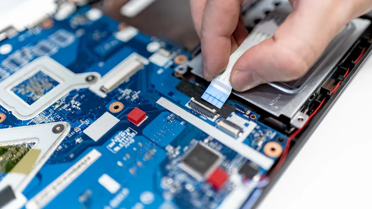
Placement
Pick-and-Place
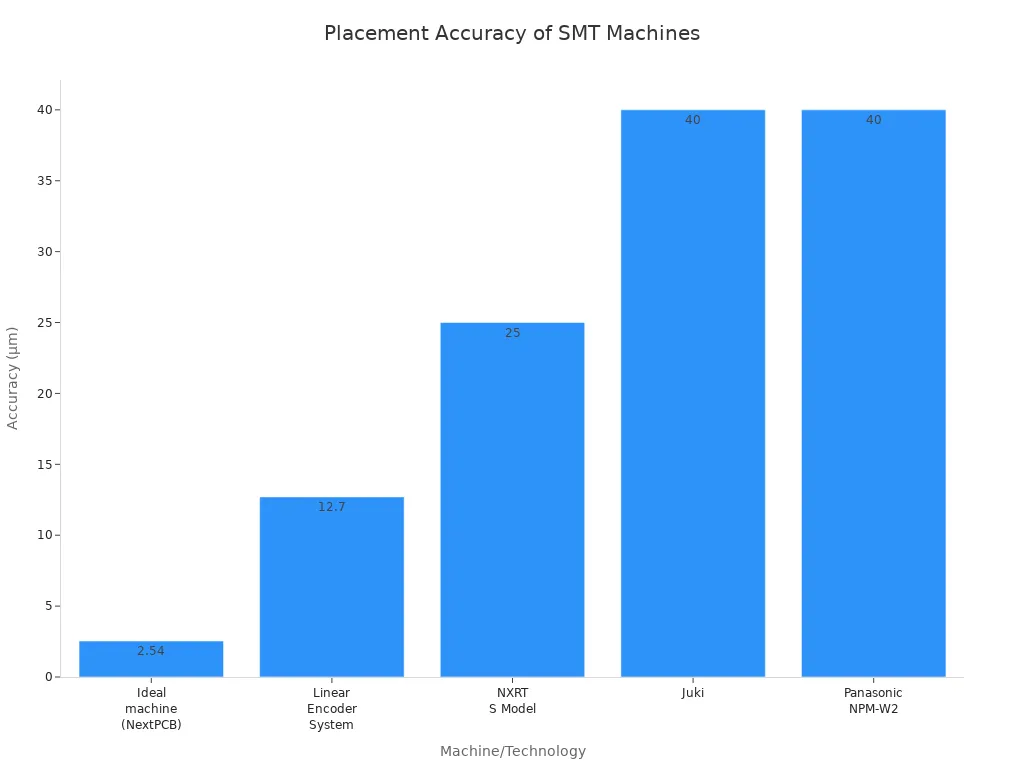
Pick and place machines put parts on the pcb fast. These machines grab each part and set it in the right spot. They can place thousands of parts every hour. Cameras and sensors help check where each part goes. Some machines are very accurate, down to 2.54 micrometers. Here is a table that shows how accurate different pick and place machines are:
Machine/Technology | Placement Accuracy |
|---|---|
Ideal machine (NextPCB) |
|
Linear Encoder System | ±0.0005 inches (~12.7 µm) |
NXRT S Model | ±25 µm |
Juki | ±0.04 mm (40 µm) |
Panasonic NPM-W2 | ±40 µm |
This level of accuracy helps the assembly process work well. The pick and place step is important for smt pcb assembly. It helps make sure soldering and connections are strong.
Manual Adjustments
Sometimes, people need to fix things the machines miss. You might see tombstoning, where a chip stands up on one end. There could be a solder bridge between pads. Sometimes, a part is not lined up right. Here are some things you might do by hand:
Fix tombstoning with hot air tools.
Take away solder bridges with solder wick and flux.
Move parts that are not lined up.
Add more solder to joints that need it.
Heat up cold solder joints to make them better.
These steps help keep the pcb assembly strong. Manual work is needed, especially for small or tricky boards.
Placement Check
After putting on the parts, you need to check them. Automated Optical Inspection (AOI) systems scan the pcb for mistakes. They find problems like misalignment, tombstoning, or solder bridges. AOI can catch up to 95% of things you can see. People also look for easy-to-spot problems. AOI uses cameras to check where each part is and how it is turned. This makes sure every part is in the right place. Checking now helps you find mistakes early and makes the smt assembly process better.
Tip: Careful checks help you avoid expensive fixes and keep your pcb assembly going smoothly.
Reflow Soldering
Oven Setup
You need to set up the reflow oven before you start to solder components on the pcb. Make sure the oven is clean and free of dust. Check that the conveyor belt moves smoothly. Set the oven zones to match your pcb and smt assembly needs. Each zone heats the board to a different temperature. This helps the solder paste melt and flow just right. Place a test pcb through the oven first. Watch how the temperature changes. Adjust the settings if you see any problems.
Temperature Profile
A good temperature profile is key for strong smt joints. You want the heat to rise slowly at first. This keeps the pcb and components safe from thermal shock. The table below shows the recommended settings for both lead-free and leaded solder:
Reflow Soldering Phase | Lead-Free Profile | Leaded Profile | Notes |
|---|---|---|---|
Pre-Heat / Soak Zone | 150°C to 180°C | 150±10°C | Shorter soak for no-clean paste |
Ramp Rate | 1.5°C–3°C/sec | Similar | Avoid rapid jumps |
Reflow Peak Temp | ~245°C | 220–230°C | Do not exceed peak |
Time Above Liquidus | 30–60 sec | Similar | Longer time can help wetting |
Cooling Rate | 2–5°C/sec | Similar | Open oven door at ~190°C for lead-free |
You should always check the profile with a thermal probe on your pcb. Adjust the oven if you see the solder paste not melting or if parts move during assembly.
Soldering Results
After reflow, look at the pcb closely. Good smt solder joints look shiny and smooth. You should not see any bridges or cold joints. If you spot dull or cracked joints, check your oven settings again. A good reflow process helps you get strong connections and reliable assembly. This step makes sure you solder components on the pcb with high quality. Careful reflow soldering keeps your pcb working well for a long time.
Cleaning
Flux Removal
After reflow soldering, you must clean off flux from your SMT circuit board. Flux can leave sticky or harmful stuff that hurts the board later. There are different ways to clean your board:
Manual cleaning is good for small jobs or test boards. You use soft brushes and special wipes with pure isopropyl alcohol (IPA) or store-bought flux removers. If you use water-soluble flux, use deionized water.
Ultrasonic cleaning uses sound waves in a liquid cleaner. This method gets into tiny spaces on crowded boards. You need to set the machine right to keep parts safe.
Automated cleaning systems are best for big batches. Machines like spray-in-air or dip cleaners use special liquids that match your flux. These machines give steady, repeatable results.
Vapor degreasing uses hot solvent vapors to melt away flux. This works well for cleaning lots of boards and lets you reuse the solvent.
Tip: Always pick a cleaning liquid that matches your flux. Try cleaning a few boards first and rinse them well so no chemicals stay behind.
Reliability Improvement
Cleaning your SMT circuit board does more than make it look nice. It keeps your board safe from future problems. If you leave flux, solder balls, or dust, you might get leaks, rust, or even shorts. These things can also hide problems when you check the board.
Taking off dirt stops things like dendrites and shorts from forming.
Clean boards help coatings stick better, which keeps out water and rust.
Good cleaning helps heat move away from parts, so they stay cool.
Even boards with “no-clean” flux should be cleaned if they are tricky or packed with parts.
Note: Cleaning often is important for strong, long-lasting SMT circuit boards. You lower the chance of big problems and make your boards better.
Inspection
AOI
Automated Optical Inspection, or AOI, is very important in smt circuit board assembly. AOI machines scan each pcb after the parts are put on. These machines use strong cameras and smart programs to look for problems. AOI checks if any parts are missing or in the wrong place. It also looks for solder bridges and cold solder joints. AOI works fast and can check many boards every hour. You get quick results and can fix mistakes right away. LTPCBA uses advanced AOI to make sure every smt circuit board assembly is high quality. AOI is great for finding problems you can see on the surface. But it might not find hidden solder joints under some parts.
Inspection Method | Defect Detection Rate | Speed (Boards per Hour) | Consistency | Notes |
|---|---|---|---|---|
AOI | 100-1000+ | High | Finds tiny defects, logs data automatically | |
Manual Inspection | 80-90% | 20-50 | Variable | Depends on skill, logs data by hand |
Manual Visual Check
Manual visual checks are still needed in smt circuit board assembly. You or your team look at the pcb with your eyes, magnifiers, or microscopes. This helps you find problems on the board. Manual checks work best for small batches or special boards. You can see things like solder bridges, missing parts, or parts turned the wrong way. But manual checks are slower and not always the same every time. People can miss small problems, especially if they are tired. Manual inspection is good for small or medium jobs, or when you need to check places AOI cannot see.
Manual inspection speed: about 5 joints per second
Best for small runs or special pcb designs
Useful for checking hidden spots AOI might miss
Reporting
After you finish checking, you need to make clear reports for every smt circuit board assembly. AOI systems from LTPCBA make automatic logs and pictures of problems for each pcb. You can look at these reports to find patterns and common mistakes. Manual checks may use written notes or checklists. Good reports help you watch quality and make your assembly better. You can use these records to teach your team and improve future smt circuit board assembly.
Tip: Always keep inspection records for every pcb. This helps you fix problems faster and keeps your smt circuit board assembly strong.
Quality Assurance
Quality assurance is the last step before the pcb leaves the factory. You must check that every pcb meets tough rules. LTPCBA uses smart systems and follows world certifications to keep quality high. Their 99.5% pass rate shows they control each step well.
Functional Testing
You test each pcb to make sure it works right. This step checks if the printed circuit board assembly can handle real use. Here are some tests you might do:
In-Circuit Testing (ICT) looks for open or short circuits and checks if each part works.
Functional Circuit Testing (FCT) acts like the pcb is in a real device.
X-ray Inspection lets you see inside the board for hidden problems.
Automated Optical Inspection (AOI) finds parts that are missing or in the wrong place.
Manual checks help you find any damage you can see.
Tip: Testing early helps you find problems and keeps your assembly strong.
Final Approval
After testing, you look at all the results. You check reports and make sure every rule was followed. LTPCBA meets rules like ISO 9001, IPC-A-610, RoHS, and UL. These certifications mean your pcba is safe and ready to use.
Certification | What It Means for You |
|---|---|
IPC-A-610 | High-quality assembly and inspection standards |
ISO 9001 | Strong quality management system |
RoHS | Safe, eco-friendly materials |
UL Listing | Product safety and compliance |
LTPCBA’s high pass rate means you get better boards with fewer problems.
Packaging
Good packaging keeps your pcb safe when shipping or storing it. You want to block static, water, and bumps. LTPCBA uses different ways to protect your pcb:
Antistatic bags and bubble wrap stop static from hurting the board.
Desiccant packets soak up water.
Vacuum sealing keeps out wet air.
ESD warning stickers remind you to be careful.
Padded boxes help stop damage from drops.

Good packaging keeps your printed circuit board assembly safe until you need it.
If you follow every step in the smt assembly process, you get good results. The table below shows how checking carefully, using accurate machines, and controlling soldering can make your pcb better:
Step | Benefit |
|---|---|
Find problems early | |
Place parts in the right spot | |
Controlled Soldering | Make strong, safe joints |
Using automated checks and keeping records helps you make fewer mistakes and makes customers happier.
LTPCBA’s skills and high standards help you do well at each step.
FAQ
What is the main benefit of using SMT over through-hole assembly?
SMT lets you place more parts on both sides of the board. You save space and make smaller, lighter devices.
How do you prevent static damage during SMT assembly?
Wear an ESD wrist strap.
Use antistatic mats.
Store parts in ESD-safe bags.
Can you reuse a PCB after removing components?
You can reuse a PCB if you remove parts carefully. Check for pad damage or lifted traces before using it again.
See Also
Effective Methods For Cleaning PCB Boards Post SMT Assembly
Common Techniques And Workflow Steps In SMT Assembly
Understanding SMT And DIP Assembly In PCBA Usage
Complete Instructions For Through Hole PCB Assembly Processes