Rigid-flex pcb board technical requirements for surface mount assembly
When using a rigid-flex PCB board, follow key technical rules. These boards need careful design for 3D layouts. Choosing the right materials is very important. Flexible parts often use Polyimide, while rigid parts use FR-4 for their job. Making these boards needs special methods to join rigid and flexible layers smoothly. This is important because industries like cars use rigid-flex PCBs to make things safer and add small, light parts.
Key Takeaways
Rigid-flex PCBs mix hard and bendable circuits for small designs.
Picking good materials, like FR-4 for hard parts and polyimide for bendable parts, is very important.
Good design and careful assembly, especially for bendable parts, make them last longer.
Keeping signals clear and blocking EMI helps rigid-flex PCBs work well.
Skilled makers like LTPCBA can make assembly easier and improve quality.
Understanding Rigid-Flex PCB Boards
Structure and Composition of Rigid-Flex PCB Boards
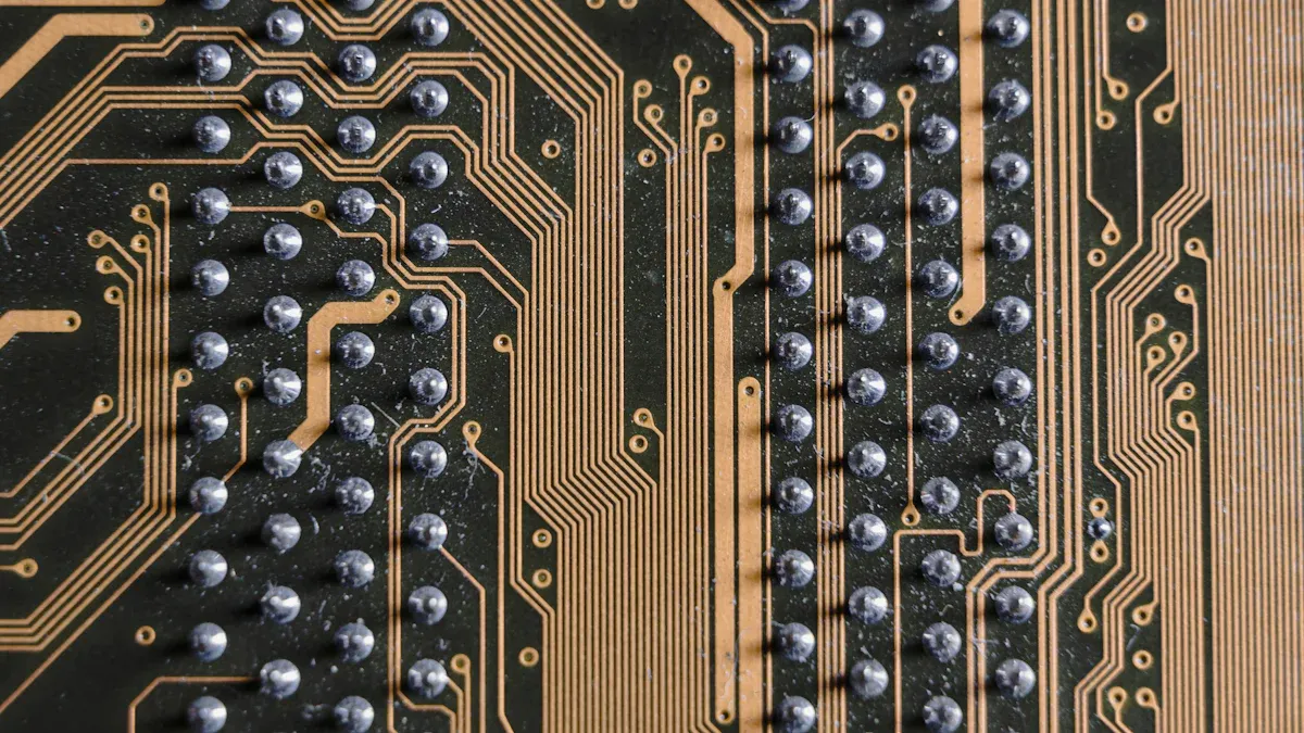
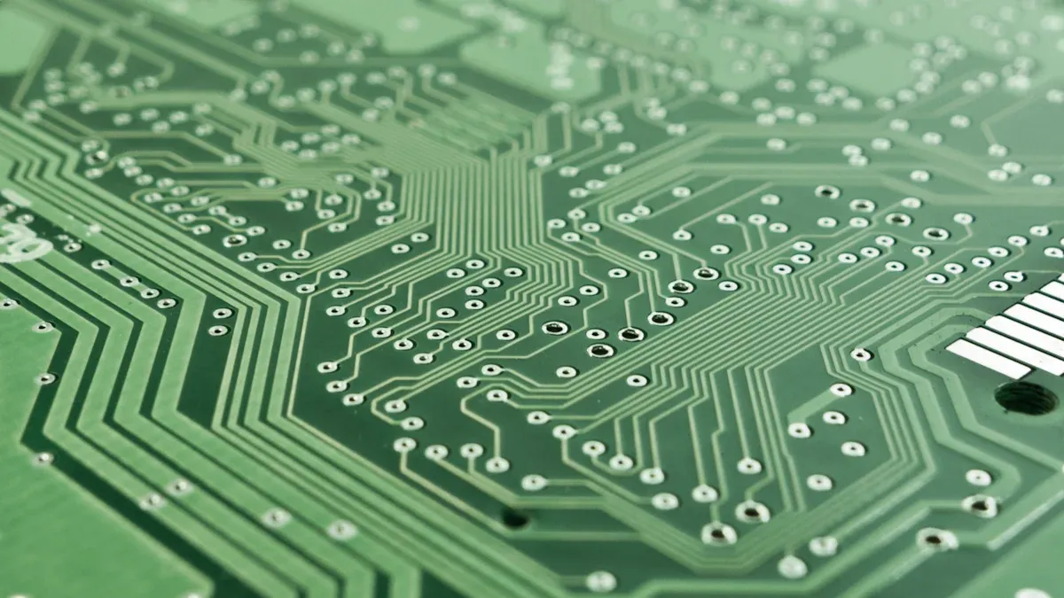
Rigid-flex PCB boards mix rigid and flexible circuits into one board. They have stiff parts joined by bendable circuits, making them fit complex designs. These boards have layers like copper foil, flexible laminates, and coverlay materials for strength and use. The flexible layers are often in the middle to help during assembly. Parts can be added to both stiff and bendable areas, with vias linking layers for electricity flow. This design makes rigid-flex PCB boards great for small and strong devices.
Component | Description |
|---|---|
Rigid-flex board | Combines stiff and bendable circuits, connecting sub-circuits in rigid PCBs. |
Materials | Core, prepreg, copper foil, flexible laminates, coverlay, and bond plies. |
Structure | Multilayered flexible sections with plated through holes for connections. |
Assembly | Parts added to both stiff and bendable areas, with vias linking layers. |
Design Considerations | Bendable layers are placed in the middle for support during assembly. |
Advantages of Rigid-Flex PCB Boards in Modern Electronics
Rigid-flex PCB boards have many benefits for modern electronics. They mix stiffness and flexibility, helping make smaller designs with fewer connections. This leads to lighter, smaller devices that work better. These boards also hold more parts, fitting more tech into tight spaces. They save money by needing fewer parts and connections during assembly.
Aspect | Description |
|---|---|
Advantages | Mix stiffness and flexibility, allowing smaller designs with fewer connections. |
Design Considerations | Needs careful planning to stay strong under stress and meet electrical needs. |
Environmental Impact | Focus on eco-friendly methods and long-lasting use in making and disposal. |
Future Trends | Used in IoT and wearable tech, improving smart device features. |
Applications of Rigid-Flex PCB Boards Across Industries
Rigid-flex PCB boards are used in many industries because they are useful and dependable. In medical tools, they help make small designs for pacemakers and hearing aids, making them more comfortable. In space tech, their light weight lowers costs and improves missions. Phones and wearable gadgets use these boards for better size and performance. They are also important in cars, telecom, and factories.
Medical devices: Used in pacemakers and hearing aids, making small designs that work well and cost less.
Aerospace: Used in satellite systems, saving weight and improving missions.
Consumer electronics: Found in phones and wearable gadgets, improving size and how they work.
Design Guidelines for Rigid-Flex PCB Boards
Layer Stack-Up and Layout Considerations
When making a rigid-flex PCB board, plan the layers carefully. Each layer setup should fit the board's purpose. For designs with odd or coreless layers, get approval first. The board's thickness should be between 0.12 mm and 2.0 mm. Core and prepreg materials can be as thin as 0.025 mm.
To make the board stronger, add extra flex layers. But this can make routing harder, especially for fast designs. Avoid using plated through holes in UHDI layers. These holes can weaken the board. Use thinner copper layers in UHDI sections, with a final thickness of 8-30 µm. For bonding pads, set a minimum size and keep tolerance within +/-10 µm.
Guideline | Description |
|---|---|
Minimum dielectric thickness | Core and prepreg can be as thin as 0.025 mm. |
Overall board thickness | Should range from 0.12 mm to 2.0 mm. |
Copper thickness in UHDI | Minimum final thickness is 8-30 µm. |
Avoid plated through holes | Especially in UHDI layers. |
Bonding pad specifications | Minimum area and tolerance of +/-10 µm must be agreed upon. |
Bending Radius and Flexibility Requirements
The bending radius is key to the board's strength and use. IPC-2223 rules say the bend radius depends on the number of layers. For single-layer boards, the bend radius should be 10 times the board's thickness. For moving parts, it should be 100 times the thickness. Multi-layer boards are not good for bending because they are less flexible.
To reduce strain, place small conductors inside the neutral bend axis. Use rounded shapes for traces and add strain relief to avoid damage. For multi-layer routing, stagger traces to spread out stress. Add tear guards to strengthen the flex material at the bend.
Layer Type | Minimum Bend Radius (inches) | Recommendations |
|---|---|---|
Single Layer | Place conductors smaller than 10 mil inside the neutral bend axis. | |
Double Layer | 10 times thickness | Maintain a minimum distance of 20 mil between PTH and bend area. |
Multi-Layer | 20 times thickness | Use tear guards to reinforce the flex material along the inside bend radius. |
Conductor Width, Spacing, and Air Gaps
The width, spacing, and gaps of conductors are very important. They help the board work well and last longer. EN 61010 safety rules give the needed clearances for different voltages. For example, a voltage of ≤150 V needs 0.5 mm clearance and creepage. For >150 V and ≤300 V, it needs 1.5 mm.
Keep traces evenly spaced to avoid electrical problems. Do not put traces too close to bending areas. This can cause stress and damage. Keep at least 0.9 mm between holes and the flex area. The flex area should be at least 2.0 mm long. These steps make the board more reliable.
Voltage Line-to-Neutral (V) | Clearance (mm) | Creepage Distance (mm) |
|---|---|---|
≤150 | 0.5 | 0.5 |
>150 ≤300 | 1.5 | 1.5 |
Tip: Test your design with paper models first. This helps you fix problems before making a prototype.
Signal Integrity and EMI Shielding
Signal quality and EMI shielding are key for a rigid-flex PCB's performance. Bad signal quality can cause data errors. Weak EMI shielding can disturb nearby devices. Fix these issues early to make a reliable PCB for tough conditions.
Keeping Signals Strong
Signal quality means how well signals move through the PCB. Fast designs often face problems like mismatched impedance, noise, and signal bounce. To keep signals strong, follow these tips:
Impedance Control: Match trace impedance with source and load. This stops signal bounce and keeps signals smooth. Controlled impedance is vital for fast designs.
Trace Design: Make traces short and straight. Avoid sharp turns to prevent signal problems. Use paired traces for fast signals to cut noise and improve quality.
Layer Stack-Up: Separate signal layers from power and ground planes. This lowers noise and gives signals a clear path back.
Decoupling Capacitors: Place capacitors near power pins. They steady voltage and reduce noise.
Tip: Use simulation tools to check signal flow before making the PCB. This saves time and avoids costly fixes later.
Improving EMI Shielding
EMI shielding stops outside interference and blocks unwanted signals from your PCB. This is crucial for sensitive devices like medical tools and space tech. Try these methods to boost EMI protection:
Grounding: Use a strong ground system. A full ground plane lowers EMI by guiding return currents easily.
Shielding Materials: Cover parts with conductive materials like copper or aluminum. These block outside signals and trap inside ones.
Trace Placement: Keep fast signal traces away from board edges. Place them near ground planes to reduce radiation.
Via Stitching: Add vias around board edges to link ground planes. This forms a shield, improving EMI safety.
Testing and Rules
Testing ensures your PCB meets EMI and EMC rules. Use simulation tools during design to spot problems early. After building, test for compliance with industry standards. This step is key for selling and long-term use.
Note: Meeting EMI/EMC rules builds trust in your product and ensures it follows regulations.
By focusing on signal quality and EMI shielding, you can make a rigid-flex PCB that works well. These steps prevent signal loss and interference, keeping your PCB dependable in any situation.
Material Needs for Rigid-Flex PCB Boards
Picking Materials for Rigid and Flexible Parts
Choosing the right materials is key for a rigid-flex PCB. The rigid parts often use FR-4, which is strong and stable. For flexible sections, polyimide is chosen for its bendability and heat resistance. Together, these materials make a board that works for both stiff and flexible uses.
Think about your project’s needs when picking materials. If your design faces high heat or frequent bending, polyimide is a great choice. Special adhesives and conductive materials are also needed for complex designs. Each material helps the board stay reliable and work well.
Tip: Check with your supplier to ensure materials meet your project’s needs.
Adhesives and Layers for Strength
Adhesives and bonding layers keep rigid and flexible parts together. They help the board stay strong under stress. Good adhesives must handle heat changes, bending, and moisture.
Manufacturers use special adhesives for flexible circuits. These adhesives stick well and stay flexible. Thermosetting adhesives are popular because they handle heat and stress well. The bonding process uses controlled heat and pressure for a strong bond.
Tests for Adhesives and Bonding Layers:
Flex Testing: Checks if flexible parts can bend without breaking.
Thermal Cycling: Tests how adhesives handle temperature changes.
AOI: Finds bonding problems during production.
Test Type | Purpose |
|---|---|
Flex Testing | Checks if flexible parts stay strong after bending. |
Thermal Cycling | Tests resistance to heat and environmental changes. |
Makes sure the board works and connects properly. |
Note: Regular testing ensures adhesives meet standards and last longer.
Thickness and Tolerance Rules
The thickness of a rigid-flex PCB affects how it works. Boards are usually 0.12 mm to 2.0 mm thick. Flexible parts use thinner materials for better bending. Core and prepreg layers can be as thin as 0.025 mm, making the board light and compact.
Manufacturers follow rules like IPC-6012 and IPC-A-610 for thickness and accuracy. These rules group PCBs into three types:
IPC Class | Description |
|---|---|
Class 1 | For basic products where function is most important. |
Class 2 | For devices needing good performance and longer life. |
Class 3 | For critical uses like medical or space systems. |
Advanced tools check thickness to meet these rules. This ensures the board works well in its environment.
Tip: Confirm thickness and tolerances with your manufacturer to avoid problems later.
Manufacturing Considerations for Rigid-Flex PCB Boards
Tolerances and Dimensional Accuracy in Production
Keeping exact sizes is very important when making a rigid-flex PCB. Correct sizes help the board fit and work well. Tools like laser cutters and AOI check for mistakes early. These tools make sure the board is made with high accuracy.
Follow the IPC-6012 rules for size limits on rigid-flex PCBs. For example, the board's thickness should be between 0.12 mm and 2.0 mm. Flexible parts need extra care because small errors can cause stress and break the board.
Tip: Work closely with your maker to match tolerances to your design.
Via Types, Placement, and Drilled Hole Cleaning
Vias connect layers in a rigid-flex PCB. Picking the right via type and spot improves how the board works. Common vias include through-hole, blind, and buried vias. Each type helps with tasks like better power flow or less EMI.
When placing vias, follow these tips:
Use big vias near parts needing more power.
Add ground vias around sensitive circuits to cut EMI.
Don’t put vias in bending areas to avoid damage.
Cleaning drilled holes is also key. Leftover bits from drilling can harm vias. Makers use fast drills and copper plating to clean and make vias conductive.
Aspect | Details |
|---|---|
Power Distribution | Big vias near high-power parts; small vias for local power. |
EMI Sensitive Areas | Ground vias around sensitive spots; spaced evenly. |
Signal Layer | Few vias for fast signals; place at trace ends. |
Thermal Expansion, Heat Management, and Soldering Reliability
Managing heat is crucial for a rigid-flex PCB to last. High heat can stretch materials, causing cracks or breaks. Use materials like polyimide or high-Tg FR-4 to handle heat well.
To cool the board, use thermal vias or heatsinks. Thermal vias move heat away from hot parts. Heatsinks keep the board’s temperature steady. These methods are vital for cars or space tech, where heat can be extreme.
Soldering must also be reliable. Bake flexible parts at 80-100°C before soldering. This removes moisture and stops layers from peeling apart.
Note: Test the board under different temperatures to ensure it works well.
Special Handling and Assembly Techniques for Flex Sections
Taking care of the flexible parts of a rigid-flex PCB is important. These parts are softer than rigid ones, so they need careful handling during assembly to avoid harm.
Handling Tips for Flex Sections
Be Gentle: Handle flexible areas softly. Do not pull, twist, or bend them too much. Too much force can cause breaks or peeling.
Use Safe Tools: Use soft tweezers or vacuum tools to avoid scratches. Stay away from sharp or metal tools that might damage the surface.
Keep Workspace Clean: Make sure your work area is free of dust. Dirt can mess up sticking and soldering.
Tip: Store rigid-flex PCBs in anti-static bags to protect them from shocks and dirt.
Assembly Techniques for Flex Sections
Hold Steady During Soldering: Use holders or jigs to keep flexible parts still. This helps with accurate soldering.
Dry Before Soldering: Heat the board gently to remove moisture. This stops peeling during soldering.
Use Controlled Heat: Apply heat evenly and avoid overheating. Use tools with temperature control for better results.
Add Protection: Use strain relief materials like Kapton tape near solder joints. This lowers stress during use.
Inspection and Testing
After assembly, check flexible parts for cracks or misplaced pieces. Use machines like AOI to ensure everything is correct. Test the board to make sure it works properly in real situations.
By using these tips, you can make your rigid-flex PCB last longer and work better.
LTPCBA’s Expertise in Rigid-Flex PCB Board Assembly
Advanced Technology and Quality Assurance Standards
LTPCBA uses advanced tools to make rigid-flex PCB boards. They use machines like AOI systems and laser drills. These tools find mistakes early and keep production accurate. By following rules like ISO, IATF, and UL, LTPCBA ensures every board meets strict quality standards.
LTPCBA focuses on making high-quality boards. They run tough tests like thermal cycling and flex testing. These tests check if boards can handle heat and bending. This makes LTPCBA a trusted choice for industries needing strong PCBs.
Turn-Key Solutions for Rigid-Flex PCB Assembly
LTPCBA handles all steps of PCB assembly. They source parts, assemble, and test the boards. This saves time and lowers costs, especially for tricky designs.
LTPCBA’s success shows in many industries. For example:
Better performance in medical devices.
Reliable use in aerospace and defense.
Fast prototypes leading to affordable small-batch production.
Here are some projects showing LTPCBA’s skills:
Product | Description |
|---|---|
Small, flexible PCB with 4-layer rigid-flex for sensors. | |
Drone Flight Controller | Strong controllers using foldable rigid-flex PCBs for stability. |
Laptop Hinge Interconnect | Multilayer rigid-flex design to stop hinge failures in laptops. |
Medical Pump Control Board | Rigid-flex design improved reliability for a medical pump system. |
These examples show how LTPCBA creates smart solutions for your needs.
Customer-Centric Approach and Industry Achievements
LTPCBA puts customers first. They offer 24-hour support and quick help when needed. With a 99.5% success rate in deliveries, they provide top-quality products.
LTPCBA’s work helps many industries. Their rigid-flex PCBs improve healthcare tools and critical aerospace systems. By focusing on quality, LTPCBA has become a trusted partner for businesses worldwide.
Tip: Work with LTPCBA to turn your ideas into reliable PCB solutions.
Understanding how to make a rigid-flex PCB board is important. It helps the board work well in surface mount assembly. Focus on good design, picking the right materials, and proper manufacturing steps. Designers, material experts, and manufacturers must work together to meet these needs. Webinars like "PCB Designers Toolbox: Rigid-flex Design Practices" and "Flex/Rigid Flex: Materials, DFM and Cost Impacts" teach useful tips, material choices, and ways to save money.
Webinar Title | Main Topics Covered |
|---|---|
PCB Designers Toolbox: Documentation for Flex and Rigid-Flex Circuit Boards | Tips for better documentation and avoiding common errors. |
PCB Designers Toolbox: Rigid-flex Design Practices | IPC rules for design that improve reliability and lower costs. |
Flex/Rigid Flex: Materials, DFM and Cost Impacts | Benefits of flex circuits, material choices, and cost-saving ideas. |
Avoiding the Most Common PCB Failure Modes by Insulectro | How to stop common failures and use good data for success. |
LTPCBA is great at making rigid-flex PCBs with high quality. They use advanced tools, follow strict rules, and focus on customer needs. Work with LTPCBA to turn your ideas into strong and creative products.
FAQ
What is the best bending radius for a rigid-flex PCB?
The bending radius changes with the number of layers. For single-layer boards, it should be 10 times the thickness. Double-layer boards need a radius 20 times the thickness. Multi-layer boards need even bigger radii to avoid breaking.
Tip: Follow IPC-2223 rules for bending radius to keep boards strong.
How can signal integrity be improved in rigid-flex PCBs?
To keep signals clear, match trace impedance and make traces short. Avoid sharp angles and use paired traces for fast signals. Separate signal layers from power planes and add capacitors near power pins to reduce noise.
Note: Use simulation tools to find and fix signal problems early.
What materials work best for rigid-flex PCBs?
FR-4 is great for rigid parts, while polyimide works for flexible areas. These materials are strong, bendable, and handle heat well. Use adhesives that resist heat and moisture for longer-lasting boards.
Section | Material |
|---|---|
Rigid | FR-4 |
Flexible | Polyimide |
How should flex sections be handled during assembly?
Be careful with flex sections to avoid damage. Use soft tools like vacuum tweezers and keep the area clean. During soldering, hold the flex parts steady with jigs and use controlled heat to stop peeling or warping.
Tip: Store rigid-flex PCBs in anti-static bags to keep them safe.
Why pick LTPCBA for rigid-flex PCB assembly?
LTPCBA uses advanced tools, follows strict quality rules, and offers full assembly services. They handle everything from materials to testing. With a 99.5% delivery success rate, LTPCBA makes reliable PCBs for industries like aerospace, medical, and electronics.
Emoji: 🌟 Choose LTPCBA for smart and trustworthy PCB solutions!
See Also
Understanding SMT And DIP Assembly For PCB Applications
Effective Strategies For Optimizing SMT Lines In PCB Production
The Influence Of Reflow Soldering Temperatures On PCB Quality