Reflow soldering temperature curves requirements in SMT assembly and processing
Accurate reflow soldering temperature curves help stop defects. They also make products work better. If you do not control the temperature, you may get more defects. This can make your costs go up by 50%.
New systems watch up to 36 temperature channels for good results.
Vacuum reflow can lower solder voids from over 40% to less than 5%.
LTPCBA uses new technology to make sure every SMT assembly is high quality.
Key Takeaways
Watch the temperature and time closely at each reflow soldering step. This helps stop problems and makes sure solder joints are strong.
Change the reflow profile for your product and solder paste type. This matches their heating needs and keeps them from getting damaged.
Use new ovens and profiling tools to check and keep steady temperature curves. This makes the quality better and saves money.
Requirements
Temperature Ranges
You must use certain temperatures for each reflow soldering stage. Each stage has its own job and needs a set temperature. The right heat stops problems and keeps solder joints strong. Look at this table to see the usual temperatures and what each stage does:
Reflow Soldering Phase | Purpose | Typical Temperature/Rate |
|---|---|---|
Preheating Zone | Warm up PCB, avoid shock | |
Soaking Zone | Even out temperature, activate flux | Hold at 140–170°C (varies) |
Reflow Zone | Melt solder, form bond | |
Cooling Zone | Solidify solder joints | Cool at 2–4°C/sec |
Always check your solder paste type and PCB design first. Picking the right temperature range gives you good results.
Timing and Control
Timing and control matter as much as temperature. You need to watch how fast the board heats and cools. Heating too fast can hurt parts. Cooling too quickly can make weak joints. Here are some important timing and control tips:
Preheating should last 40–120 seconds with a ramp rate of 1–3°C/sec.
The soaking zone usually holds for 20–30 seconds.
The peak temperature in the reflow zone should last 30–60 seconds.
Cooling should not exceed 4°C/sec.
Tip: Use thermal profiling tools to check your oven. Calibrate often to keep every batch the same.
Good timing and control help stop warping, bridging, or cold soldering. This means better quality and fewer problems in your SMT assembly.
Reflow Soldering Zones

Preheat
The preheat zone is the first step in reflow soldering. In this stage, the PCB and its parts get warmer slowly. You must control how fast the heat goes up. If you heat too fast, parts can break or solder paste can splash. Experts say to keep the slope rate between 0.75°C/s and 2.0°C/s. Most PCBs need a preheat from 150°C to 190°C. This step usually takes 60 to 120 seconds.
Parameter | Range |
|---|---|
Preheat temperature | 150°C to 190°C |
Preheat time | 60 to 120 seconds |
Preheat slope rate | 0.75°C/s to 2.0°C/s |
Note: Keeping the temperature steady and the conveyor moving at the same speed helps stop problems in this step.
LTPCBA uses special ovens that control the heat very well. These ovens keep the ramp rate even and protect your parts.
Soak
The soak zone is the next step. Here, the PCB stays at one temperature so heat spreads out evenly. This step also makes the flux in the solder paste work and gets rid of leftover chemicals. The soak temperature is usually between 155°C and 200°C. The board stays in this zone for 60 to 120 seconds. If you soak too slow, oxidation can happen. If you soak too fast, gases can get trapped and cause problems.
Aspect | Details |
|---|---|
Soak temperature range | |
Soak time | 60 to 120 seconds |
Key process | Even heating, flux activation |
You can change the soak zone by adjusting the oven’s second zone or the conveyor speed. For example, raising the soak temperature a little can lower tombstoning by more than 10%. LTPCBA’s machines let you make these changes very accurately.
Reflow
The reflow zone is the most important part. Here, the temperature goes above the solder’s melting point. This melts the solder and makes strong joints. For lead-free solder, you need at least 230°C, but most use 235°C to 250°C. The board should stay above the melting point for 30 to 90 seconds. Too much heat can hurt parts, but too little heat can make weak joints.
Parameter | Value/Range | Notes |
|---|---|---|
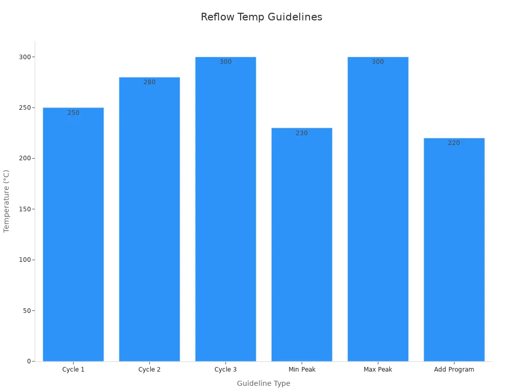
Minimum peak temperature | 230°C | Needed for proper solder joint |
Typical peak temperature | 235°C to 250°C | Lead-free solder |
Maximum peak temperature | Up to 300°C | For special cases, depends on PCB and components |
Time above liquidus (TAL) | 30 to 90 seconds | Ensures full soldering |
Tip: Keep the conveyor speed the same so every board gets the right amount of heat.
LTPCBA’s reflow lines use machines and sensors to watch every board. These systems keep the temperature just right.
Cooling
The cooling zone is the last step in reflow soldering. Here, the temperature drops so the solder joints get hard. How fast you cool the board changes the solder’s structure. Fast cooling (10°C/min to 100°C/min) makes flat, strong layers. Slow cooling can make bumpy layers that are not as strong. You should cool at about 4°C/sec or 5°C/min.
Note: Cooling at the right speed helps stop cracks and keeps solder joints strong.
LTPCBA uses air to cool the boards and checks the speed closely. This keeps the solder joints strong and stable. The company also uses X-ray checks to find hidden problems after cooling.
Why Stable Zones and Precise Control Matter
Keeping the temperature steady and the conveyor speed the same is very important for good reflow soldering. If the temperature changes too much or the conveyor slows down or speeds up, you can get problems like cold joints or bent parts. LTPCBA uses special ovens, cameras, and machines to get the best results. The company also uses laser-cut stencils, accurate placement machines, and X-ray checks to make sure every board is high quality.
Profile Adjustment
Product Factors
You must change the reflow soldering profile for each product. Every board and part can have its own needs. The table below lists important product factors and how they change your temperature settings:
Product Factor | How It Affects Profile Adjustment |
|---|---|
Solder Paste Composition | Different alloys and flux types melt at different points. You need to set the profile right to stop problems. |
Component and Pad Size & Geometry | Big parts and pads heat up slower. You might need more soak time for even soldering. |
PCB Surface Finish and Cleanliness | Dirty or rusty surfaces need stronger flux and careful heating. |
Thermal Characteristics | Heavy or heat-sensitive parts need special ramp and peak temperatures. |
Defect-Related Factors | Problems like tombstoning or voids mean you should change ramp rates and soak times. |
Temperature Profile Types | Pick Ramp-Soak-Spike or Ramp-to-Spike depending on your assembly. |
You can use thermal analysis tools, like thermocouples, to check heat spread. This helps you pick the best profile for your board.
Solder Paste Types
You also need to think about the solder paste you use. Each paste type has its own needs in reflow soldering. Here are some key differences:
Low-temperature solders, like bismuth ones, melt at lower heat and need special profiles.
SAC alloys (lead-free) need higher peak heat, usually from 235°C to 250°C.
The ramp rate and soak time change how well the solder sticks and how strong the joints are.
Bismuth pastes can leave oxide behind, so you may need extra cleaning.
Some parts or boards do not like too much heat, so you must change the profile to keep them safe.
Tip: Always match your temperature profile to your product and solder paste for the best results.
Equipment & Monitoring
Oven Settings
You need to set the oven just right for good results. Modern ovens use smart controls and sensors to keep heat steady. These ovens can change heat, humidity, and speed by themselves. Here are some things advanced ovens can do:
Sensors and cameras watch the process as it happens.
Digital tools help you find problems like uneven heat or slow belts.
Automatic alerts tell you if something is wrong.
A good oven lets you set ramp rate, soak time, and peak heat for each step. For example, you can set a ramp rate from 1 to 3°C per second in the ramp zone. You can set a peak heat from 230 to 250°C in the reflow zone. These settings help stop damage and make strong solder joints.
Profiling Tools
Profiling tools help you check and control the heat curve during reflow soldering. You can use thermocouples to measure heat on different board spots. New profilers collect data as it happens and send it to your computer. Some tools can test many oven settings in less than a minute and pick the best one for your board. This makes it easy to set up the right profile, even if you are new. The Process Window Index (PWI) shows if your profile is safe.
Tip: Use profiling software to adjust your oven and keep every batch the same.
LTPCBA Quality Assurance
LTPCBA uses advanced machines and strict checks to make sure your boards are top quality. The company follows ISO 9001 and ISO 13485 rules for quality. Automated Optical Inspection (AOI) systems look for defects and parts that are not lined up. LTPCBA also meets RoHS and UL safety rules. These steps help you get safe, reliable, and high-quality PCB assemblies every time.
Quality Measure | What It Means for You |
|---|---|
ISO 9001, ISO 13485 | Consistent quality and safety |
AOI | Fewer defects and better performance |
RoHS, UL | Safe and eco-friendly products |
Quality Control
Solder Joint Inspection
You must check each solder joint to be sure your boards work. AOI and 3D SJI systems help you find problems fast. These systems show you data right away, like how many boards pass or fail. This helps you know if your process is working well. For example, Omron’s 3D-SJI system uses SPC tools to watch quality by line and model. You can see yield rates, look at real defects, and find out what causes them. LTPCBA checks every board carefully to reach a 99.5% pass rate. This gives you trust in every shipment.
LTPCBA’s support team helps you understand results and fix problems quickly.
Troubleshooting
If you find problems, you need a plan to fix them. First, check your reflow oven. Make sure the heating parts and blower motors work right. Use profiling tools to see if the oven heats evenly. Then, check how you handle parts and look for temperature or humidity issues. Certified engineers can help you change your reflow profile to fix things like solder voids or poor wetting. Sometimes, you need to bake parts to find hidden problems. If you still have trouble, work with your vendors to solve it. Patience and teamwork help you fix even hard soldering problems.
Continuous Improvement
You can make your process better by using data from each step. Most solder problems start during stencil printing. SPI machines measure paste volume and where it goes. These machines help you find problems early and fix them before they get worse. Check your solder paste storage, stencil cleaning, and thermocouple placement often. Try new things, like nano-coatings, to make stencils better. Change your reflow soldering profile for new materials or smaller parts. By watching data and making small changes, you keep getting better solder joints and assembly results.
You must use the correct temperature curves for strong solder joints. Check and change your process often to avoid mistakes. Automated systems can find problems early and help make better boards. LTPCBA uses special tools and careful checks to keep quality high. By keeping your process current, you get good results and save money.
FAQ
What happens if you use the wrong reflow temperature curve?
You may see weak solder joints, more defects, or damaged parts. Always follow the correct curve for your board and paste.
How often should you check your reflow oven profile?
You should check the profile before each new batch or when you change products. This keeps your process safe and reliable.
Can you use the same profile for all solder pastes?
No. Each solder paste has its own needs. Always match the profile to the paste type for the best results.
See Also
Typical Reflow Soldering Issues In SMT And How To Prevent
Real-Time Temperature Curve Testing For Reflow Soldering In PCBA
Essential Wave Soldering Techniques For Effective SMT Assembly
Why Nitrogen Reflow Soldering Matters For Automotive And PCBA
The Role Of Precise Temperature Profiling In SMT Reflow Quality