The process requirements for reflow soldering in SMT processing
You are important in making good pcb assemblies by paying attention to every step in the reflow soldering process in smt. Careful control in surface mount technology helps you lower mistakes, which can make manufacturing costs go up by as much as 50%. Using machines to check and setting the right temperature help soldering work well and make sure printed circuit boards are dependable.
Key Takeaways
Get materials ready by checking solder paste quality. Use the correct stencil for the job. Keep the workshop clean and controlled to stop problems.
Watch the temperature during preheating, soaking, reflow, and cooling. This helps make strong solder joints and stops damage.
Inspect and test carefully using AOI and X-ray. Clean well and control the process to find problems and make sure PCB assemblies work well.
Reflow Soldering Steps
Material Preparation
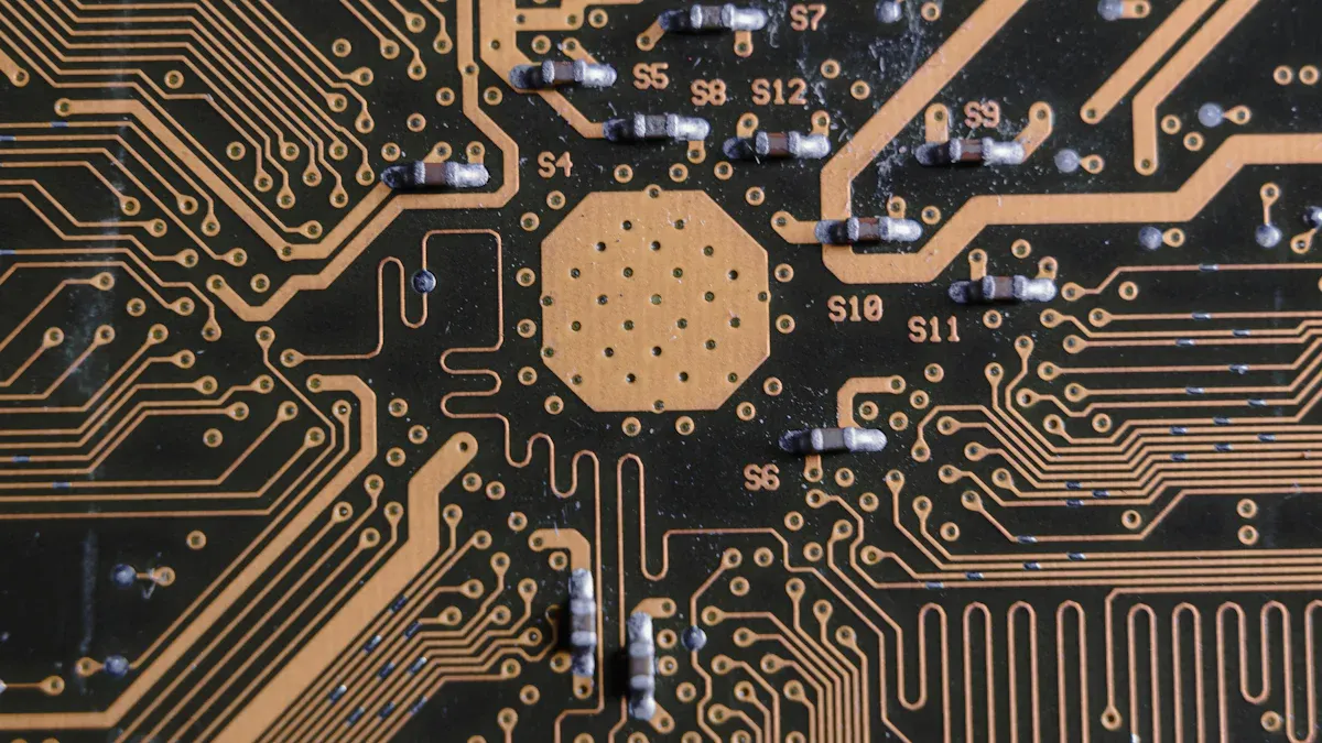
First, you get all your materials ready. Good preparation stops problems later. You must check the solder paste for the right alloy and particle size. The paste should have 80-90% metal powder by weight. The flux in the paste cleans off oxidation and helps the solder move. Store the paste at 0-10°C. Keep your workshop at 25°C and 50% humidity. Stir the paste before using it so it is smooth.
You also need to look at the stencil. The thickness, hole size, and shape of the stencil change how much solder paste goes on the pcb. If you use the wrong stencil, you might get too much or too little paste. This can cause problems like solder bridging or weak joints. LTPCBA uses special machines to control these steps and keep quality high.
Tip: Always check the solder paste’s expiration date and keep it cool.
Solder Paste Application
Next, a solder paste printer puts the paste on the pcb. The printer spreads the paste through the stencil onto the pads. You must control the amount, area, and height of the paste. Too little paste makes weak connections. Too much paste can cause solder bridges and short circuits.
Parameter | Description | Importance |
|---|---|---|
Volume | Amount of solder paste deposited | Ensures reliable joints, prevents cold joints |
Area | Surface area covered by solder paste | Prevents connectivity issues |
Height | Height of solder paste deposits | Too low causes weak connections, too high causes bridging |
You can use 3D solder paste inspection to find problems. Automated systems, like those at LTPCBA, spot issues like not enough solder, solder bridges, or odd shapes. These systems use AI and can find up to 90% of defects. This step is important for quality and helps you avoid problems in the oven.
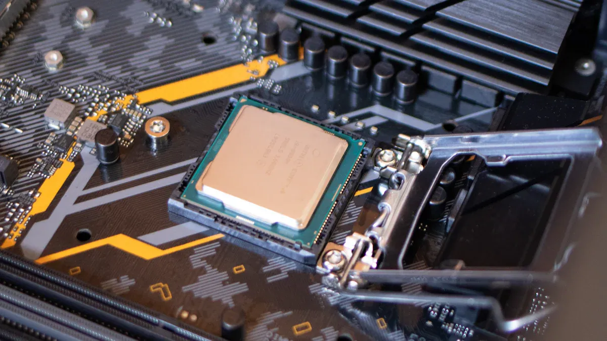
Component Placement
After the paste is on, you put the components on the pcb. Machines pick and place each part quickly and accurately. You must line up each component with the pads. If a part is not in the right spot, you might get tombstoning or open circuits.
Statistical Parameter | Description and Importance | Typical Tolerance/Target |
|---|---|---|
Alignment (X, Y, θ) | Ensures parts are centered and oriented | ±50 μm or ±50% of pad width |
Area Coverage | Solder paste covers 80-100% of pad | Prevents poor connections |
Solder Paste Volume | Avoids weak joints or bridging |
LTPCBA uses pick-and-place machines and checks the process to keep placement exact. This step is very important for good soldering and strong pcb assemblies.
Preheating
Now, you put the pcb into the reflow oven. The preheating stage slowly warms up the pcb. The temperature should rise about 3°C per second. It should reach at least 150°C but not go over 200°C. This stage lasts 60 to 120 seconds.
Phase | Parameter | Recommended Value | Details |
|---|---|---|---|
Preheat | Temperature Rise Rate | 3°C/sec | Controls how fast the pcb heats up |
Preheat | Min Temperature | 150°C | Minimum for flux activation |
Preheat | Max Temperature | 200°C | Prevents damage to components |
Preheat | Duration | 60-120 seconds | Time spent in preheat zone |
Preheating helps get rid of solvents in the solder paste and gets the assembly ready for the next step. If you heat too fast, you can hurt the pcb or cause problems. LTPCBA’s ovens use careful controls to keep this step safe and effective.
Thermal Soak
The thermal soak stage keeps the pcb at a steady temperature. This lets the flux work and spreads heat evenly. The soak usually lasts 60 to 120 seconds. The temperature stays up to 30°C above the solder’s melting point. This step helps stop problems like solder balling or voids.
Soak time can go up to 400 seconds for heavy boards.
Temperature stays steady for the first 30 seconds, then rises slowly.
Temperature changes should stay within 5°C for sensitive parts.
If you rush this step, you might get cold joints or voids. If you go too slow, you waste time and energy. LTPCBA watches this stage closely to keep quality high.
Reflow Phase
In the reflow phase, the oven heats the pcb above the solder’s melting point. The temperature goes up at 1 to 3°C per second. The solder melts and makes the final joints. You keep the pcb above the melting point for 30 to 60 seconds. This lets the solder flow and connect the parts.
Parameter | Value/Range | Explanation |
|---|---|---|
Maximum Slope (Ramp Rate) | 1.0°C to 3.0°C/second | Prevents component cracking. |
Time Above Reflow | 30 to 60 seconds | Ensures proper joint formation. |
The highest temperature depends on the solder type but is often 245°C for lead-free solder. If you heat too much, you can damage the pcb or cause problems. If you do not heat enough, the solder may not melt all the way. LTPCBA’s ovens use special settings to stop these problems and make sure soldering is good.
Cooling
After reflow, the oven cools the pcb. The cooling speed changes how the solder joints form and how strong they are. A fast cooling rate, like -2.5°C per second, makes stronger joints and stops unwanted compounds from growing. A slow rate can make thick, uneven layers and weaker joints.
Cooling Rate (°C/sec) | Solder Alloy | Key Observations on Reliability and Joint Formation |
|---|---|---|
-2.5 | Lead-free (95.5Sn/3.8Ag/0.7Cu) | Stronger joints, less intermetallic growth after aging. |
-0.5 | Lead-free | Thicker, uneven layers, lower reliability. |
-2.5 | Tin/Lead (63Sn/37Pb) | Thin, uniform layer, stronger joints. |
-0.5 | Tin/Lead | Less uniform, more defects. |
LTPCBA uses ovens with special cooling zones to keep the rate steady. This step is very important for quality and for making sure your pcb assemblies last a long time.
Note: Good cooling stops cracks and helps your solder joints last longer.
Quality Assurance with LTPCBA
Inspection and Testing
Strong inspection and testing help keep pcb assemblies working well. LTPCBA checks every pcb at each step to make sure it is good. Automated Optical Inspection (AOI) looks for surface problems, soldering mistakes, and parts in the wrong place. X-ray inspection can see inside the pcb to find hidden problems like cracks or voids. Continuity testing checks if every connection works. Functional testing makes sure the pcb does what it should. Environmental stress testing pushes the pcb to handle heat and shaking. These steps help stop defects and keep soldering results strong.
Quality Assurance Statistic / Protocol | Description / Impact |
|---|---|
First Pass Yield (FPY) | Between 95% and 98%, showing high efficiency and reliability in assembly. |
Waste Rate | Less than 5% of boards wasted, showing tight process control. |
AOI | Finds surface problems and soldering mistakes early, so less rework is needed. |
X-ray Inspection | Finds hidden solder joint problems like cracks and voids. |
Functional Testing | Checks if the pcb works in real-life situations. |
Cleaning and Final Assembly
Clean surfaces help make strong solder joints. LTPCBA’s team uses isopropyl alcohol to clean off oxides before soldering. They use good flux and solder to help the solder flow and stick well. Skilled workers watch oven temperature and solder amount to stop defects. They use 2D vision and 3D X-ray scans to check every joint. Electrostatic discharge protection keeps pcb parts safe during assembly. These steps help avoid defects and make sure your printed circuit board lasts a long time.
Cleaning takes away dirt and oxides.
Good soldering and cooling give strong connections.
Skilled repair steps fix joints if needed.
Process Control
LTPCBA uses process control at every step. The company uses data to find defects and make quality better. Pick-and-place machines are 99.95% accurate, so parts go in the right spot. The oven keeps the right temperature for reflow soldering. This helps stop defects and keeps soldering results steady. AOI and in-circuit testing happen at every stage. The quality program checks every pcb before it ships. LTPCBA meets ISO, UL, and IATF standards, so you know the quality is high.
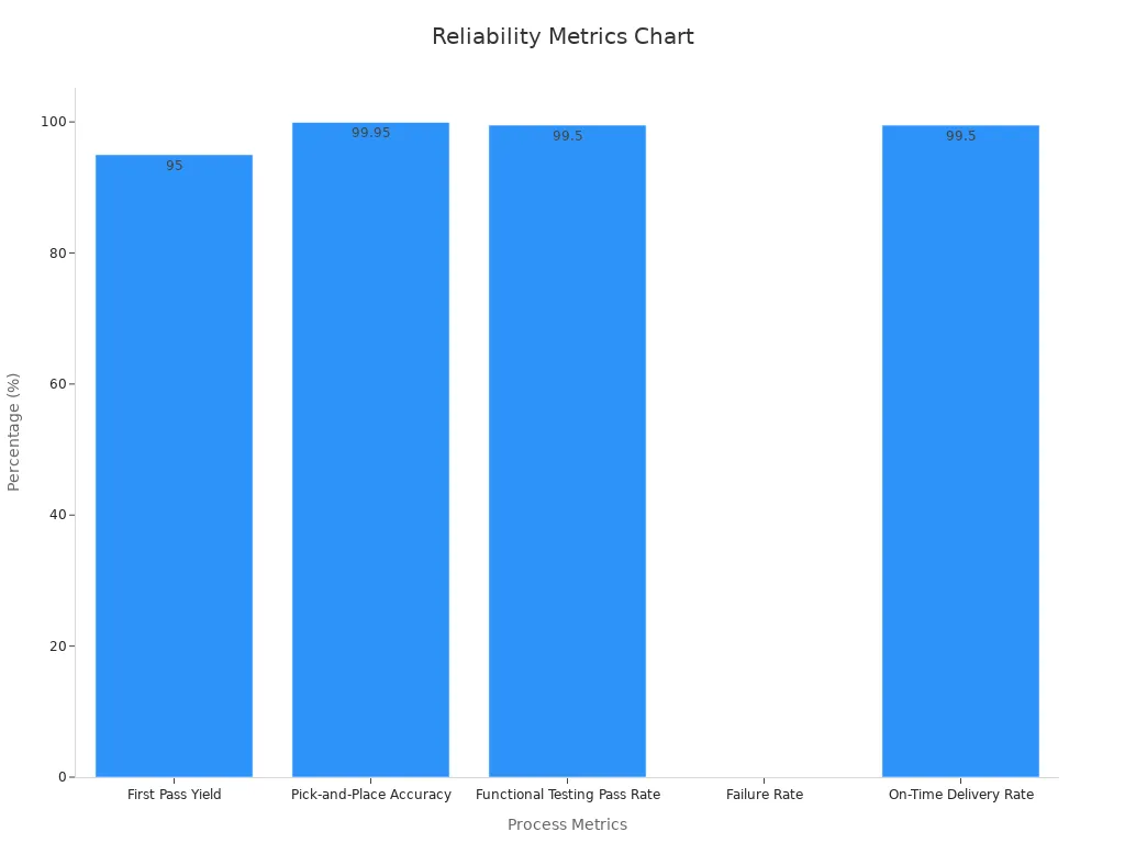
You get a 99.5% pass rate and on-time delivery. These numbers show LTPCBA’s process control and oven management help you avoid defects and get reliable pcb assemblies.
You can make strong PCB assemblies if you follow each step carefully. Watch the temperature, timing, and check your work often. The table below lists important process settings. These settings help you stop mistakes and make better quality.
Parameter | Recommended Value | Effect on Quality |
|---|---|---|
Ramp Rate | Stops thermal stress | |
Soak Zone Temperature | 150-160°C | Makes sure solvents go away |
Peak Temperature | 235-245°C (lead-free) | Helps form strong solder joints |
Time-Above-Liquidus | 30-90 seconds | Makes solder stick better |
Pick LTPCBA for great process control and top results.
FAQ
What is the most important factor in reflow soldering?
You must control the temperature profile. This step helps you avoid defects and ensures strong solder joints.
How does LTPCBA check for soldering defects?
You get AOI and X-ray inspection at every stage.
Inspection Type | What It Finds |
|---|---|
AOI | Surface defects |
X-ray | Hidden joint issues |
Can you use lead-free solder in reflow soldering?
Yes, you can use lead-free solder. You need to set the peak temperature between 235°C and 245°C for best results.
See Also
Step-By-Step Guide To Reflow Soldering Through-Hole Parts Post-SMT
Identifying And Preventing Typical Reflow Soldering Defects In SMT
Essential Wave Soldering Standards For Effective DIP Assembly Processing
Fundamental PCB Board Criteria For Successful SMT Manufacturing
The Effect Of Temperature Zones On PCB Quality During Reflow