How to Achieve Flawless BGA Assembly with Quality Control
Flawless BGA assembly depends on rigorous Quality Control Measures at every step. Multi-stage inspections use advanced tools like X-ray and AOI to catch hidden defects early. LTPCBA commits to innovation and high standards, ensuring each board meets strict requirements for reliability, performance, and customer satisfaction.
Key Takeaways
Flawless BGA assembly depends on strict quality control at every step to catch defects early and ensure reliable connections.
Advanced inspection tools like X-ray and Automated Optical Inspection reveal hidden and visible defects, improving product quality and reducing failures.
Following industry standards and continuous process improvements helps manufacturers deliver high-quality, dependable BGA assemblies that satisfy customers.
BGA Assembly Basics
What Is BGA?
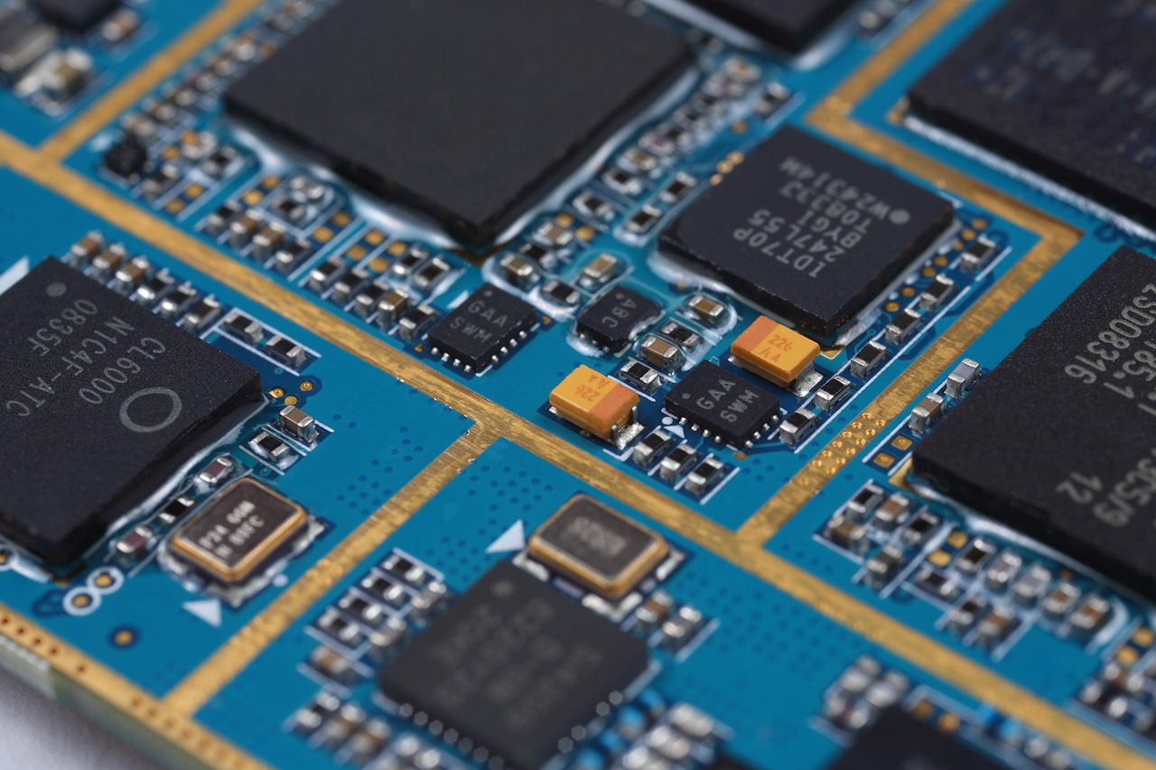
Ball Grid Array (BGA) refers to a type of surface mount component that uses small solder balls to connect the chip to the printed circuit board (PCB). Engineers use BGA packages because they allow for more connections in a smaller space compared to older pin-based designs. Technical literature describes several BGA variants, such as CBGA (ceramic substrate), PBGA (plastic substrate), FBGA (fine pitch), and FCBGA (flip chip molded). For example, Intel’s micro-FCBGA package for mobile processors uses 479 solder balls arranged in a 26x26 grid, with a 1.27 mm pitch and an empty inner area. These packages differ in substrate material, thickness, and mounting technology, which helps meet different performance needs.
Tip: BGA components rely on Surface Mount Technology (SMT), which attaches parts directly to the PCB surface using solder.
Key Challenges
BGA assembly presents several engineering and reliability challenges. The main issue involves the mechanical reliability of solder joints, especially under thermal stress and vibration. Solder joints can develop micro cracks or even fail at the bottom interface between the BGA ball and the copper pad. Lead-free solder alloys, such as SAC405, offer better resistance to thermal strain and vibration compared to traditional tin-lead solders. However, problems like improper oven reflow profiles, insufficient solder, PCB flexing, and contamination can still cause defects.
Common challenges include:
Solder joint fatigue from thermal cycling
Micro cracks and insufficient solder
Component issues like moisture sensitivity
Manufacturers address these risks by using advanced simulation methods, strict process controls, and careful design choices to improve reliability and reduce failure rates.
Common Defects
Typical Issues
BGA assembly often faces several recurring defects that can impact product reliability. Technicians frequently observe voids in solder joints, which occur when trapped gases form empty spaces during the reflow process. While small voids may not always reduce reliability, excessive voiding can weaken connections and require corrective action. Misalignment between the BGA and PCB leads to incorrect electrical connections. Missing solder balls or ball leakage results in open circuits and non-functional devices. Inconsistent standoff height, where the BGA sits unevenly on the PCB, can cause weak joints. Other common issues include:
Solder bridging, which creates unintended connections between pads and causes short circuits.
Non-wetting pads, where solder fails to adhere due to incomplete reflow or contamination.
Cold solder joints, which appear brittle and unreliable.
The popcorn effect, where moisture inside components expands during reflow, causing cracks or shorts.
Note: X-ray inspection helps detect hidden defects like voids and misalignment, which are difficult to see with the naked eye.
Causes
Several factors contribute to these defects. Poor solder paste quality or incorrect application often leads to insufficient or excessive solder, resulting in weak joints or bridging. Package warpage and improper PCB or stencil printing parameters can cause misalignment and inconsistent standoff heights. Statistical analysis shows that early solder paste inspection data can predict later defects, such as head-in-pillow, with high accuracy. Complex assembly processes also increase the risk of errors, as more steps introduce more opportunities for mistakes. Mechanical and thermal stresses during manufacturing or operation can create cracks or dents in solder balls. Industry studies highlight that reviewing and optimizing each process step, from material selection to thermal profiling, reduces defect rates and improves overall assembly quality.
Quality Control Measures
Pre-Soldering Steps
Quality Control Measures begin before any soldering takes place. LTPCBA sets up a clean, well-lit, and organized workspace to prevent contamination and errors. Technicians prepare all tools and materials, checking each for defects or compatibility issues. They inspect PCBs for cleanliness and correct pad alignment, confirming that the solder mask covers only the intended areas.
Solder paste application is a critical step. LTPCBA uses automated stencil printers to apply solder paste with precision. Solder Paste Inspection (SPI) systems then check the volume, area, and height of each deposit. These systems use 2D and 3D imaging to catch defects like insufficient solder or irregular shapes early. By following IPC-7527 and ISO 9001 standards, LTPCBA ensures that every board meets strict requirements for quality and consistency.
Industry Standard | Role in Quality Control | Support for Step-by-Step Actions |
|---|---|---|
IPC-7527 | Solder paste printing and inspection | Guides optimization of solder paste application |
IPC-A-610 | Component placement and soldering quality | Ensures precision and defect reduction |
ISO 9001 | Quality management system | Reinforces systematic quality control |
UL 796 / UL 796F | Product safety standards | Ensures safety compliance |
RoHS | Restricts hazardous substances | Ensures environmental compliance |
LTPCBA’s focus on solder paste quality, pad design, and stencil accuracy reduces the risk of defects later in the process. The company’s use of Solder Mask Defined (SMD) and Non-Solder Mask Defined (NSMD) pads improves solder joint reliability, especially for BGA components.
In-Process Controls
During assembly, Quality Control Measures continue at every stage. Automated pick-and-place machines position BGA components with high accuracy. Operators verify placement using visual inspection and automated systems. LTPCBA’s process includes real-time monitoring of environmental factors like temperature and humidity, which can affect soldering results.
Reflow soldering is a key step. LTPCBA uses programmable reflow ovens with precise thermal profiles. These ovens heat the boards in controlled stages—preheat, soak, reflow, and cooling—to ensure strong, reliable solder joints. Real-time data logging tracks temperature and process stability. Statistical analysis, such as Statistical Process Control (SPC), helps identify trends and optimize parameters. This approach reduces defects and repair costs by quickly adapting to changes in production.
Automated X-ray Inspection (AXI) systems check hidden solder joints under BGA packages. These systems detect voids, bad solders, and missing parts that visual inspection cannot see. LTPCBA also uses a documented quality audit process, including two different X-ray validation platforms, to ensure compliance and reliability.
A dedicated problem-solving team reviews any non-conformances. They analyze defects using data, simulation, and testing, then implement preventive measures and technology upgrades. This continuous improvement cycle keeps defect rates low and product quality high.
Post-Soldering Checks
After soldering, Quality Control Measures focus on final inspection and testing. Automated Optical Inspection (AOI) systems use high-resolution cameras and advanced algorithms to detect surface defects, such as solder bridges, insufficient solder, or misaligned components. AOI supports defect tracking and process improvement through SPC statistics.
For BGA and other hidden joints, X-ray inspection provides a non-destructive way to check for internal voids, solder ball shape, and pin welding quality. In-Circuit Testing (ICT) verifies electrical connections, while Functional Testing (FCT) simulates real-world conditions to catch latent failures.
Manual visual inspection serves as a final check, especially for complex or critical areas. Operators document any defects and follow standardized rework procedures. LTPCBA’s management system records and categorizes defects, enabling root cause analysis and continuous process optimization.
LTPCBA’s commitment to international standards, advanced technology, and systematic Quality Control Measures has resulted in a 99.5% pass rate for product delivery. The company’s approach ensures that every board meets the highest standards for reliability and performance.
Tip: Consistent documentation and feedback loops help LTPCBA improve processes and maintain high quality over time.
Inspection Technologies
Visual inspection cannot guarantee flawless BGA assembly. Many defects in BGA solder joints remain hidden beneath the component, making them invisible to the naked eye. Manufacturers rely on advanced inspection technologies to ensure every connection meets strict quality standards.
X-Ray
X-ray inspection plays a vital role in BGA assembly. This technology allows technicians to see inside the PCB and examine solder joints hidden under the BGA package. Automated X-ray Inspection (AXI) detects issues such as voids, opens, shorts, and misalignments. AXI systems provide a non-destructive way to verify all connections, even those beneath dense chip packages. Studies show that pairing X-ray with boundary scan and functional testing increases defect detection rates in complex assemblies. LTPCBA uses high-resolution X-ray platforms to inspect every BGA joint, ensuring compliance with IPC-A-610 acceptance criteria.
AOI
Automated Optical Inspection (AOI) uses high-resolution cameras and intelligent software to check for surface defects. AOI systems detect problems like insufficient solder, bridging, misaligned components, and foreign particles. This method supports detection of fine-pitch faults and works well for high-volume production. AOI measures component placement and solder fillet dimensions, comparing them to IPC-A-610 standards. LTPCBA integrates AOI at multiple stages, from solder paste inspection to post-reflow checks, to catch defects early and maintain process control.
Electrical Testing
Electrical testing verifies that every circuit functions as intended. In-Circuit Testing (ICT) checks for shorts, opens, and correct component placement. Functional Testing (FCT) simulates real-world operating conditions to confirm performance. JTAG boundary scan adds another layer of assurance for complex boards. LTPCBA combines these electrical tests with X-ray and AOI to deliver comprehensive quality assurance. This multi-method approach ensures each board meets international standards and customer requirements.
Note: Advanced inspection methods and statistical monitoring, such as Statistical Process Control (SPC), help LTPCBA maintain a 99.5% pass rate and deliver reliable BGA assemblies.
Best Practices
Checklist
A flawless BGA assembly process relies on a clear set of best practices. Technicians and engineers should follow these steps to reduce defects and improve reliability:
Inspect PCB surfaces for cleanliness and correct pad alignment before assembly.
Apply solder paste using automated stencil printers and verify with Solder Paste Inspection systems.
Use Design for Testing (DFT) principles to ensure proper component spacing and test point placement.
Confirm correct solder mask application between pads to maintain electrical integrity.
Optimize drill bit size and surface-mount pad sizing for manufacturability.
Place test traces on sensitive signal lines to monitor performance during testing.
Monitor thermal profiles during reflow to prevent solder joint fatigue and micro cracks.
Combine X-ray and Automated Optical Inspection to detect both hidden and visible defects.
Studies show that aging at high temperatures and long thermal cycling can weaken solder joints. Micro-alloyed lead-free solders and careful control of thermal profiles help maintain reliability. Multi-method inspection strategies, such as X-ray and AOI, catch more defects and reduce rework time.
LTPCBA Advantages
LTPCBA stands out by integrating advanced Quality Control Measures at every stage. The company uses automated systems and high-resolution inspection tools to ensure each board meets strict standards. Customers benefit from quick response times, with quotations delivered in 2-3 working days and 24-hour technical support. LTPCBA’s commitment to international standards and continuous process improvement results in a 99.5% pass rate. The team’s expertise and dedication to customer satisfaction make LTPCBA a trusted partner for flawless BGA assembly.
Rigorous Quality Control Measures at every stage reduce BGA defects and improve reliability.
Metric | Impact |
|---|---|
Higher product quality | |
Customer Satisfaction | Better user experience |
LTPCBA’s expertise and advanced technology help customers achieve dependable results. Choose trusted providers to ensure flawless BGA assembly. |
FAQ
What makes BGA assembly different from other PCB assembly types?
BGA uses solder balls under the chip for connections. This design allows more connections in less space and improves electrical performance.
How does LTPCBA ensure high BGA assembly quality?
LTPCBA uses automated inspection tools, strict process controls, and follows international standards. The team checks every board with X-ray, AOI, and electrical testing.
Why is X-ray inspection important for BGA assembly?
X-ray inspection finds hidden defects under BGA components. Technicians use it to check solder joints that cannot be seen with the naked eye.
See Also
Innovative Methods For Reliable BGA Electronics Assembly
Expert Strategies To Perfect BGA Assembly Processes
Effective Ways To Prevent Errors During BGA Assembly
Key Quality Control Steps For Through Hole PCB Assembly
Quality Assurance Practices In Modern Turnkey PCBA Factories