7 Critical Quality Control Checkpoints in Professional Through Hole PCB Assembly
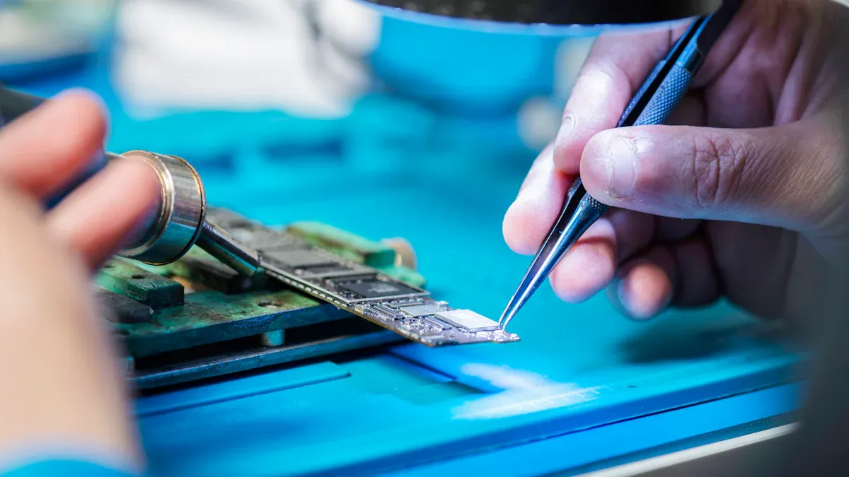
Quality control is essential to ensure that circuit boards function effectively. Poorly manufactured PCBs can fail or malfunction. At LTPCBA, parts are placed meticulously, and thorough inspections are conducted at various quality control checkpoints. They utilize safe soldering materials and employ specialized machines for verification. Every step adheres to stringent guidelines to guarantee high quality. These quality control checkpoints ensure that your circuit boards perform at their best.
Key Takeaways
Carefully look at PCB layouts and designs before building them. This helps find errors early and lowers the chance of problems.
Clean and cut component leads to make soldering stronger and better. This stops rust and keeps connections from breaking.
Watch soldering heat and time to make strong joints. Good heat control avoids damage and keeps the work high-quality.
Pre-Assembly Quality Control Checkpoints
Checking PCB Layout and Design
Before starting assembly, check the PCB layout carefully. Make sure the layout follows design rules and manufacturing needs. A final design check finds layout mistakes that could cause problems. Reviewing the Bill of Materials (BOM) ensures all parts are correct and complete. Gerber files confirm the board is ready for production.
Clear assembly drawings and instructions help during manufacturing. A team design review checks every part of the circuit board design. This step ensures the design meets standards and reduces defects. Designers make changes to meet requirements, improving reliability and cost-effectiveness of the PCBs.
Examining Component Details and Compatibility
Checking component details is important for good PCB performance. Look at the quality, availability, and cost of each part. This ensures the parts work well with the board design and avoids supply problems.
Carefully inspect components for damage like cracks or scratches. Problems like surface dirt or heat damage can affect the board's reliability. Fixing these issues early saves money and improves production.
Using performance data helps make smart design choices. This ensures the PCB works well and stays within budget. Paying attention to these details builds a good reputation and keeps customers happy. It also makes the manufacturing process smoother and more dependable.
Component Preparation for Printed Circuit Boards
Cleaning and Trimming Component Leads
Cleaning component leads is an important step for good PCB quality. It removes dirt, oil, and harmful residues that can cause problems. These residues may attract water, leading to rust and weak solder joints. Cleaning also helps coatings stick properly, so they don’t peel off later.
Cutting leads to the right length is just as important. It lowers the chance of short circuits and gives a neat look. Cleaning and trimming also stop unwanted growth caused by leftover chemicals. This growth can create paths that may cause your PCB to fail. By doing these steps, you improve solder strength and make your PCB more reliable.
Ensuring Correct Component Orientation
Placing components correctly is key for your PCB to work well. Misplaced parts can mess up signals and cause interference. Proper placement makes assembly faster and easier.
Always check the direction and polarity of each component. Wrong placement can lead to poor performance or even PCB failure. Correct orientation ensures the board works as planned and meets design needs. By focusing on this, you save time, cut costs, and keep your PCBs high quality.
Soldering Process Quality Control
Monitoring Soldering Temperature and Time
Keeping the soldering temperature and time just right is very important. If the heat is too low, the solder won’t melt well. This can cause weak connections. Too much heat can harm parts or the circuit board. Watching these settings closely helps your PCBs work better.
The soldering process has three main steps:
The preheating zone warms the board slowly to avoid damage.
The soaking phase spreads heat evenly and activates the flux.
The reflow zone melts the solder paste at a high temperature.
The best peak temperature is between 235°C and 250°C. This depends on the type of solder paste used. Careful control of heat and timing in each step makes strong solder joints. Following these steps reduces mistakes and improves PCB quality.
Inspecting Solder Joint Formation
Checking solder joints is key to making reliable PCBs. Good solder joints create strong electrical links and hold parts firmly. Bad joints can cause loose connections or circuit failure.
Different methods help find solder joint problems:
How It Helps | |
|---|---|
Non-destructive Testing | Finds issues without harming the parts. |
Destructive Testing | Confirms problems and uncovers hidden defects. |
Micro-sectioning | Shows detailed views of solder joints and their layers. |
Dye Penetrant Testing | Spots cracks and poorly wetted joints. |
Electrical Characterization | Tests aging and finds flaws under stress. |
These methods catch problems like cracks, gaps, or bad wetting. Fixing these early ensures your PCBs are high quality. Regular checks also follow design rules and make your boards more dependable.
Visual Inspection of PCBs
Looking closely at PCBs helps keep their quality high. By checking the board, you can find problems early. This step is key to making sure PCBs work well.
Finding Soldering Problems
Soldering mistakes can make PCBs stop working. Careful checks can find issues like weak joints or too much solder. Machines like Automated Optical Inspection (AOI) help spot surface problems. These include scratches, stains, and soldering errors. AOI checks boards at different steps to keep quality steady.
AOI also finds problems in PCB assemblies, like wrong part placement. It checks if parts are in the right direction and soldered correctly. AOI costs less than X-ray tests and avoids repeated mistakes. Using these checks ensures your PCBs are made to high standards.
Spotting Misaligned Parts
Misaligned parts can cause signals to fail or act up. Visual checks catch misplaced parts or soldering mistakes early. Fixing these stops bigger problems later. This method also finds small flaws that don’t affect signals but hurt the board’s design.
Visual checks work well for complex boards where machines might miss things. They adjust to new problems and keep PCBs working as planned. Fixing misalignment early makes boards more reliable and avoids delays in production.
Electrical Testing for Assembled PCBs
Electrical testing is important to check if your PCBs work well. It helps find problems early, saving money and time. This step ensures your circuit boards meet high-quality standards. It is one of the most important checks in making PCBs.
Conducting Continuity Testing
Continuity testing checks if all connections on the PCB are complete. It makes sure there are no broken paths or wrong connections. This test confirms the board matches the design rules.
Special tools like multimeters or testing machines are used for this. These tools send a small current through the board to check resistance. Low resistance means the connection is good. High resistance or no reading shows a problem. This test finds mistakes in the design or during manufacturing.
By doing continuity testing, you ensure the board follows design rules. It also catches big errors before moving to the next step. This saves time and avoids wasting resources. It makes your PCBs more reliable and ready for use.
Performing Functional Testing
Functional testing checks if the PCB works as it should in real life. It tests how the board handles tasks it is designed for. This makes sure the board performs well under normal conditions.
During this test, the board is checked for handling electrical loads. It also tests how it reacts to signals and performs its tasks. This helps find problems before the board is used.
Functional testing improves the PCB's reliability in many ways:
It checks if the board works as planned in real use.
It finds problems early, stopping failures later.
This step is key to keeping PCBs high quality. Adding functional testing to your process ensures reliable boards. This builds trust with customers and improves your reputation.
Tip: Use both continuity and functional testing together. This ensures your PCBs are both well-connected and work properly. These steps protect the design and quality of your boards.
Advanced Testing Techniques in PCB Assembly
Environmental Stress Testing (Thermal Cycling and Vibration)
Environmental stress testing checks if PCBs handle tough conditions. It mimics real-life challenges like temperature changes and shaking. Testing this way finds weak spots and makes PCBs more reliable.
Thermal cycling tests how solder joints hold up to fast temperature changes. Quick shifts can stress the joints, causing cracks or breaks. BGA parts are especially at risk from temperature shocks. Vibration testing checks how PCBs handle shaking during use. This test shows if the board can resist wear and tear.
Problem Type | What It Means |
|---|---|
Fast temperature changes can crack solder joints. | |
Solder Joint Strength | Harsh conditions test if solder joints stay strong. |
Vibration Resistance | Tests if shaking causes damage or weakens the board. |
HALT testing adds stress like heat and vibration until the board fails. This helps find design flaws and limits, ensuring strong and reliable PCBs.
X-Ray Inspection for Hidden Solder Joints
X-ray inspection finds hidden problems in solder joints. It uses 2D and 3D images to spot issues regular checks miss. This ensures PCBs meet strict quality standards.
Common problems include tiny holes, extra solder, and bad connections. These weaken the board and make it less reliable. X-rays also find lifted pads, misplaced parts, and hidden cracks. Catching these early saves money and improves quality.
Problem Type | What It Means | Why It Matters |
|---|---|---|
Solder Voids | Small holes in solder that weaken connections. | Stops failures and boosts reliability. |
Solder Bridges | Extra solder causing short circuits. | Avoids expensive fixes. |
Open Circuits | Bad soldering leading to broken connections. | Prevents board malfunctions. |
Lifted Pads | Pads not sticking properly, causing issues. | Ensures better performance. |
Misaligned Parts | Parts placed wrong, affecting how the board works. | Stops functional problems. |
Cracks and Layer Issues | Hidden damage that can cause big failures. | Improves safety and durability. |
X-ray checks lower mistakes and waste, saving money over time. They are key for making high-quality PCBs used in fields like aerospace and healthcare.
Final Quality Assurance by LTPCBA
Reviewing Documentation and Test Results
The last step in making PCBs is checking all documents. This ensures the board design follows rules and works properly. At LTPCBA, careful reviews help catch problems early. Fixing these issues improves reliability and reduces mistakes.
LTPCBA uses advanced tests like in-circuit, functional, and optical checks. These tests make sure your PCBs work well in real-life situations. The First Pass Yield (FPY) score, between 95% and 98%, shows their success. Also, less than 5% of boards are wasted, saving materials.
Design for Manufacturability (DFM) makes production easier and lowers errors. By following strict rules and doing detailed checks, LTPCBA turns your designs into top-quality PCBs.
Packaging and Shipping Inspection
Good packaging and shipping keep your PCBs safe during delivery. LTPCBA uses anti-static bags to stop damage from static electricity. Vacuum-sealing, moisture barrier bags, and desiccants protect against water. Humidity cards show if moisture gets inside. These steps follow IPC 1601 guidelines for safe handling.
Custom packaging can be made to fit your needs. Bar codes and labels are added for easy tracking. Certificates of Conformance and other papers are included if requested.
By focusing on keeping boards dry and clean, LTPCBA ensures they arrive safely. These careful checks show LTPCBA’s promise to deliver strong, reliable products.
Following these seven steps helps make strong and lasting PCBs. LTPCBA focuses on quality to give great results. Improving your methods can make your PCBs work better. It also helps you earn your customers' trust. Begin using these steps now for improved results.
FAQ
Why is through-hole PCB assembly more dependable than surface-mount assembly?
Through-hole assembly creates stronger connections. It handles stress and heat better, making it ideal for tough conditions.
How does LTPCBA make sure solder joints are high quality?
LTPCBA uses tools like AOI and X-ray to check for problems. These methods find issues early, ensuring solder joints are strong and reliable.
Why is testing PCBs under stress important?
Stress testing copies real-life conditions. It finds weak spots in parts and solder, making sure PCBs work well even in harsh environments.
See Also
Important Technical Considerations for VIPPO PCB SMT Assembly
Evaluating Reliability: Through Hole vs. SMT PCB Assembly
Essential Quality Control Tips for SMT Solder Paste Printing