PCBA for SCADA Systems and Industrial Communication
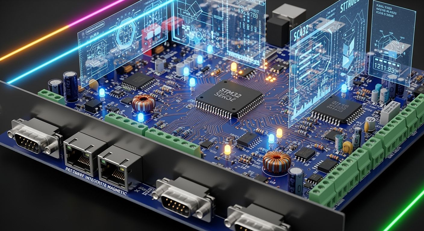
You need total control over modern factory equipment. Supervisory control and data acquisition systems deliver this control. A custom industrial communication pcba forms the core of this network. It connects every plc, HMI, and drive directly to scada host software. This connection allows continuous data collection and real-time monitoring across your facility.
Reliable pcba design guarantees strict signal control and high noise protection. You master scada in the industry 4.0 era by using strong control hardware. Proper layout design helps control heavy EMI, prevents ground loops, and handles wide temperature changes. Protective layers preserve signal protocol integrity during industrial automation. This industrial control foundation secures continuous environmental data monitoring and long-term control reliability.
Key Takeaways
Choose deterministic Ethernet transceivers for SCADA systems to ensure fast, real-time control across factory automation networks.
Send fast dual-wire signals at a steady 100 ohms resistance to prevent signal loss and protect delicate network lines.
Create double-pattern circuit board designs for important parts to avoid factory delays when factory supplies run out.
Use protective coatings and cooling systems to safeguard delicate control boards stored within hot factory boxes.
PCBA Design for SCADA Protocols and Hardware
Deterministic Ethernet vs Fieldbus Protocols
Modern factory communication network architectures connect supervisory control and data acquisition hardware directly to plant machines. You must choose the right industrial communication protocol to keep data flowing safely across your facility. Traditional Modbus TCP runs over standard Ethernet. It offers low-cost monitoring and data collection when response times near tens of milliseconds are fine. However, Modbus TCP provides no real-time control guarantees.
Deterministic industrial Ethernet protocol options handle tight machine timing much better. Real-time protocols prioritize critical motion data over standard TCP/IP network traffic.
PROFINET Class | Communication Behavior | Board-Level Implication |
|---|---|---|
Physical layer | Standard 100 Mbps or 1 Gbps Ethernet with Cat5e/Cat6 cabling, switches, or fiber. | Use a standard Ethernet PHY and magnetics; no PROFINET-specific physical layer is required. |
NRT | Standard TCP/IP for configuration, diagnostics, and non-time-critical data. | Standard Ethernet MAC/PHY with a TCP/IP stack is sufficient. |
RT | Cyclic I/O bypasses TCP/IP stack; typical cycle times 1-10 ms. | Standard Ethernet hardware can be used; the protocol stack must handle PROFINET RT frame handling. |
IRT | Hardware-scheduled communication below 1 ms with sub-microsecond jitter. | Requires ASIC-based switches or MCUs with integrated real-time switch hardware; time slots are reserved in hardware. |
Your pcba design must support these physical demands. A robust industrial ethernet pcb uses a dedicated real-time switch chip to bypass the processor stack during high-speed control cycles. This dedicated hardware structure protects determinism while your scada system gathers monitoring data from each connected node.
Transceiver ICs for Real-Time PLC and VFD Data
Choosing the right physical layer transceiver IC ensures fast real-time data flow across your system. High device counts in industrial automation create thermal and noise challenges. You need transceivers that keep scada communication stable while working next to noisy drives. A low-latency transceiver shortens loop cycle time. This rapid response allows one plc communication module to monitor many connected devices without losing packet integrity.
Requirement Category | PCBA Design Requirement | Protocols Supported |
|---|---|---|
PHY selection and clocking | Use an industrial Ethernet PHY with RMII for 10/100 Mbps to reduce pin count; place a stable 50 MHz reference clock close to the PHY with a solid ground return. | Modbus TCP, PROFINET, EtherNet/IP |
Differential pair routing | Route TX/RX pairs as 100 ohm controlled-impedance differential pairs; keep high-speed digital lines separated from the analog differential pairs. | Modbus TCP, PROFINET, EtherNet/IP |
Isolation and EMC | Provide at least 1500 Vrms galvanic isolation; place isolation magnetics next to the port; use a copper ground cutout under the magnetics and bridge it with 2.2 nF, 2 kV Y-rated capacitors. | Modbus TCP, PROFINET, EtherNet/IP |
PROFINET IRT support | For PROFINET IRT, include a specialized ASIC or MCU with an integrated real-time switch so that time-critical frames bypass the TCP/IP stack. | PROFINET |
EtherNet/IP support | Use standard TCP/IP/UDP and standard Ethernet infrastructure; no proprietary chipset is needed, which simplifies component sourcing. | EtherNet/IP |
Modbus TCP support | Encapsulate Modbus over TCP/IP; no real-time hardware is needed, so a low-cost microcontroller with a standard Ethernet MAC/PHY is sufficient. | Modbus TCP |
Packed industrial ethernet pcb layouts often lack fans. Heat builds up fast inside sealed control boxes. Running chips past their temperature limits creates data errors, causes signal timing jitter, and breaks the network. You must pick industrial-grade transceivers built for a -40°C to 85°C operating range. These parts handle continuous heat and strong electrical noise easily. Choosing low-power transceivers lowers self-heating in small enclosures. This design plan guarantees solid real-time control, protects scada data accuracy, and brings full industry 4.0 automation to your plant.
High-Speed Routing for Industrial Communication
High-speed physical layer routing protects signals in a factory communication network. Motor control noise from heavy machinery continuously interferes with transmission lines. You must build board traces that preserve real-time control operations across your whole facility. Ethernet physical layer protocol standards mandate high signal integrity. Continuous physical signal monitoring ensures long-term operational quality in harsh environments. Proper routing design preserves signal quality in harsh environments.
Differential Impedance and Physical Layer Layout
Reliable industrial ethernet pcb design requires tight impedance control for all high-speed lines. You must match trace geometry precisely to avoid signal reflection and loss. Standard Ethernet routing targets a differential impedance of 100 Ω between paired data lines. On standard FR-4 board stack-ups with a dielectric constant of 4.3 to 4.7, a starting geometry uses 6 mil to 8 mil trace widths with 6 mil to 8 mil spacing. Alternatively, a 5 mil trace width with 8 mil spacing provides another standard starting point for 100 Ω differential pairs.
Parameter | Recommendation | Context / Note |
|---|---|---|
Differential impedance | 100 Ω | Target impedance for Ethernet differential pairs |
Example trace geometry | 5 mil width / 8 mil spacing | Starting layout for 100 Ω differential impedance on 1.6 mm FR-4 |
Inter-pair clearance | At least 3× trace width | Follow the 3W rule to reduce crosstalk between adjacent traces |
Routing length | Keep trace length ≤ 4 inches | Limits high-frequency signal attenuation between PHY and connector |
Keep differential pair spacing stable from the transmitter to the receiver. Random changes in spacing cause impedance discontinuities across data signal paths. Maintain a continuous reference plane underneath all high-speed traces. You must avoid plane splits under differential routing to prevent return path disruptions. Keep the trace length from the PHY chip to the connector under 4 inches. Limit intra-pair skew below 50 mil and inter-pair skew below 200 ps. Limit each trace to a maximum of two via transitions. Board layout control ensures accurate data delivery. These control layout practices keep real-time plc communication stable during intense industrial automation cycles.
Galvanic Isolation Moats and Surge Protection
Industrial automation equipment faces electrical surges, high common-mode voltages, and ground loops. An industrial communication protocol needs dedicated layout protection to maintain physical data transfers. A robust transmission protocol keeps frames moving without errors. You protect real-time control circuits by placing isolation magnetics and transient voltage suppression components right next to the physical port. A custom pcba layout isolates high voltages from sensitive logic circuits.
Keep trace lengths under 25 mm between the Ethernet connector and TVS devices to limit transient voltage pickup.
Cut a complete power plane keepout beneath the Ethernet magnetics module to prevent switching noise from coupling into board power rails.
Connect 75-ohm resistors from each Ethernet line to a 2-kV TVS array referenced to the enclosure chassis for Bob-Smith termination.
Place a TVS array directly across the protected signal line as a shunt element to direct incoming electrical surges away from sensitive chips.
You shield internal scada board sections by splitting the ground plane into isolated zones. Bridge this isolation moat using high-voltage safety capacitors. This layout prevents ground loops from corrupting control and scada monitoring signals. The main control node receives clean power while the design choice blocks high-voltage noise spikes before they reach sensitive processor pins.
Proper surge networks sustain total control over data integrity across industrial networks. Clean signals allow continuous scada environmental data monitoring across noisy production plants. Careful physical layout protects your industrial ethernet pcb against extreme electrical spikes. Strict routing control maintains constant data throughput across every connected scada node.
Component Lifecycle and Supply Chain Resilience
Dual-Footprint Strategies for Critical ICs
You must maintain stable operational control over factory networks. Modern electronic parts become outdated quickly. Integrated circuit life cycles shorten rapidly. In fact, about 15% of components disappear from the market annually. You protect your industrial pcba design by laying out dual-footprint patterns for critical chips.
Dual-footprint design allows you to drop alternative physical package styles onto a single board space. You can solder a secondary pin-compatible chip if the main part goes out of stock. This strategic design prevents production stops. You preserve real-time control without needing to wait for long component lead times.
Long-Life BOM Management for Systems
Industrial control equipment demands a 10-to-15-year product lifecycle. You achieve this long-term control reliability through careful bill of materials management. You can optimize costs by placing standard RS485 for local I/O while reserving heavy Ethernet communication parts only for primary connections. Furthermore, you must select distributors with ISO 9001:2015 quality management systems. These suppliers deliver full product data traceability and certificates of conformance.
You must lock key component part numbers in your bill of materials to maintain strict process control during manufacturing.
You must actively track potential component risk indicators. Early monitoring prevents sudden supply shortages.
Risk Indicator | Impact on Manufacturing |
|---|---|
End-of-life status | Manufacturers stop production due to low demand or technology changes. |
Component life-cycle status | Unplanned part death forces high-cost redesigns without early forecasting. |
Replacement availability | Sourcing aging parts gets difficult as market supply decreases. |
Single-source components | Unhedged single-source parts create severe production disruption risks. |
Regular bill reviews help you track raw supply data on part availability. You capture real-time market data to manage component changes. This proactive data tracking lets you secure control hardware long before shortages occur. Proper control planning secures continuous scada data flow across your industrial network. You keep every connected scada node active over many years of continuous industrial plant control.
DFM and Harsh-Environment Protection
High-Density Layout and BGA Escape Routing
Complex SCADA board chips require exact layout rules. You should pick dog-bone fanout for 0.80 mm pitch BGA parts. This setup lowers assembly risks when making industrial control boards. Dog-bone routing links BGA pads to outer vias with short traces. You can place 0.20 mm drilled vias with 0.45 mm pads on top layers. Keep a small 0.1 mm gap between BGA pads and trace paths.
Good assembly settings protect high-density hardware. Non-solder-mask pads prevent solder bridges during thermal cycles. Use Type 4 lead-free paste to get stable reflow results. A nitrogen reflow process stops oxidation while heating the parts. Peak temperatures between 235°C and 250°C create clean solder joints. Automated x-ray testing keeps solder voids under 10 percent. These automated checks give you total quality control over every key node. Smart pad layouts improve joints and protect long-term board reliability.
Conformal Coating Selection for Heavy Industry
Rough factory settings destroy bare circuit board surfaces over time. Strong chemical fumes and moisture ruin thin copper control traces. Protective coatings shield copper paths from continuous environmental damage. You can brush acrylic coatings at 50 to 100 μm thickness for easy repairs. Acrylic materials soften above 80°C under severe operational heat. Silicone coatings at 75 to 150 μm thickness offer strong moisture defense for automation gear.
Coating choices change how heat moves away from active drive parts. Standard 25 to 75 µm coatings trap excess heat around hot components. Very thin nano coatings at 2 to 10 µm add little thermal resistance. Nano layers help power switches drop internal heat quickly. Thin covers allow quick field soldering and simplify board repair work. Factory crews get live system data from shielded control hardware. Good environmental covers stop data errors and keep SCADA signals precise. You keep full control over tasks while protecting data across the plant network. Smart design picks ensure smooth data flow during vital SCADA control tasks.
Validation Testing and Box Build Integration
Automated Inspection, ICT, and Latency Testing
Checking every assembled board before installation prevents system failures. Automated optical systems check part placements and solder quality. In-circuit testing then verifies component values and pin continuity across physical board paths. Strict quality controls prevent defective hardware from reaching plant floors.
After structural testing, functional checks evaluate real-time data communication speeds. These tests send high-speed frames through each port to measure timing delays. You confirm proper control by checking for sub-millisecond response times under heavy traffic. This testing ensures that connected modules maintain smooth data tracking during normal operations.
Enclosure Integration and Thermal Management
Sealed cabinets protect sensitive control electronics from dust and moisture. Motor drives generate extreme internal heat inside these sealed spaces. Drive power losses usually equal 3–8% of their total rating. A 15 HP drive can release 0.45–1.2 kW of heat into a panel. Poor heat management lets cabinet temperatures reach 200°F and disrupt system performance.
You must choose effective cooling methods to protect hardware and maintain uninterrupted control system monitoring:
Flange-mount the drive so its main heatsink extends outside through a sealed gasket. This setup moves most heat outside the main cabinet.
Select a fiberglass cabinet when external mounting is impossible. Fiberglass radiates twice as much heat as stainless steel to keep interiors cool.
Install compact thermoelectric cooling units on small sealed enclosures. These systems clear excess heat without breaking protective cabinet seals.
Mount heavy power hardware inside a separate climate-controlled room while running signal lines to motor areas.
Avoid using filtered vent fans in wet locations because open vents destroy water-resistant cabinet seals.
Using these cooling methods keeps sensitive monitoring hardware running smoothly. Proper heat management prevents signal delays, protects data quality, and maintains steady control across all production areas.
You achieve factory performance by building strong supervisory control and data acquisition infrastructure. Strategic pcba design links every plc directly to central networks. You protect operational reliability by combining robust protocol hardware, tight noise isolation, dual-footprint supply planning, and protective conformal coatings.
Robust hardware design guarantees real-time monitoring and sustained control across every industrial facility.
This holistic engineering plan secures critical data transfers across your entire industrial automation environment. High-speed signal routing prevents physical communication errors. Careful heat management preserves system stability. You gain total control over complex plant operations while positioning your infrastructure for scalable industry 4.0 expansion. Dependable control hardware maintains constant network uptime, secures data flow, and drives modern factory automation.
FAQ
How Do You Select Hardware for SCADA Communication?
You pick a factory network setup based on your speed needs. Every system follows specific timing rules. Industrial Ethernet choices provide quick control for active machinery. Simple serial options work well for basic data collection. You must protect signal quality to keep automation running smoothly.
Why Does Fast Ethernet Matter for a PLC Node?
Fast Ethernet skips normal network delays. Your controller chip sends key signals within tiny fractions of a second. This quick timing guarantees exact data tracking across factory machines. You stop high-cost shut downs by installing dedicated control hardware.
How Do You Shield Industrial Board Signals from Electrical Noise?
You protect network lines with magnetic parts and surge suppression chips. Keep twin trace paths matched closely at 100 ohms. Separate quiet logic zones from noisy power parts. These smart layout choices supply clean data while keeping continuous system control during big power spikes.
What Validation Steps Secure Long-Term System Performance?
Automated camera checks and speed tests verify physical board builds under heavy stress. You push high data traffic through each port to check response times. This full testing step ensures top control over field network speed. Reliable circuit boards keep SCADA connections working inside tough factory setups.
See Also
Exploring The Critical Role Of Industrial Serial Screen PCBA Systems
Demystifying Printed Circuit Board Assembly Definitions In Electronics Design
A Complete Beginner Guide To Essential PCBA Electronic Components
Strict Manufacturing Standards Required For Medical Grade PCBA Processing
Strategic Electronic Component Sourcing Best Practices For PCBA Manufacturing
