How BGA Assembly Works in SMT PCB Manufacturing Step by Step
You follow a precise process in pcba bga assembly smt pcb manufacturing. First, you apply solder paste to the pads. Next, you place the BGA component with high accuracy. Then, you use reflow soldering to create strong connections. Finally, you inspect and test each board. LTPCBA ensures quality and uses advanced technology.
Key Takeaways
Proper preparation of PCBs and BGA components is crucial. Cleanliness and controlled storage prevent defects and ensure reliable connections.
Using the right solder paste composition and applying it correctly is essential for strong solder joints. Inspect solder paste application to catch issues early.
Advanced inspection methods like X-ray and automated optical inspection are vital. They help detect hidden defects and ensure the reliability of BGA components.
BGA Assembly Process
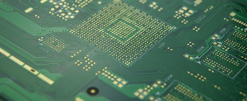
PCB and Ball Grid Array Preparation
You start the bga assembly process by preparing both the PCB and the ball grid array components. Cleanliness and proper handling are essential. You store boards in a dry, stable environment with controlled temperature and humidity. You use covers or packaging to prevent dust and moisture. You label each unit and inspect stored boards regularly. Before assembly, you preheat boards to remove any absorbed moisture. You use ultrasonic cleaners to clean PCBs, which helps prevent defects like cold welding and voids.
You follow strict industry standards to ensure quality. Here is a table showing the most important standards for PCB and ball grid array preparation:
Standard Code | Description |
|---|---|
IPC-A-610 | Acceptability of Electronic Assemblies |
IPC-J-STD-001 | Requirements for Soldered Electrical and Electronic Assemblies |
IPC-J-STD-002 | Solderability Tests for Component Leads |
IPC-J-STD-005 | Requirements for Soldering of BGA Components |
IPC-J-STD-020 | Moisture/Reflow Sensitivity Classification |
IPC-J-STD-033 | Handling, Packing, Shipping, and Use of Moisture/Reflow Sensitive Components |
IPC-J-STD-075 | Guidelines for the Design of BGA Packages |
IPC-7525 | Guidelines for the Design of PCB Assemblies |
IPC-7526 | Guidelines for the Design of BGA Assemblies |
IPC-7527 | Guidelines for the Design of PCB Assembly Processes |
You also follow ISO and RoHS guidelines to ensure high build quality and restrict harmful substances. You inspect the ball grid array components for any damage or contamination. You use X-ray inspection to check solder joints under the ball grid array, since these joints are not visible with optical techniques.
Tip: Thorough cleaning and inspection before assembly help you avoid defects and ensure reliable connections in pcba bga assembly smt pcb.
Solder Paste Application
You apply solder paste to the PCB pads using stencil-printing. This step is critical for successful bga assembly. You select the right solder paste composition, often using lead-free solder with 99.7% tin and 0.3% copper. Other mixtures may include tin, silver, copper, or bismuth. The solder paste must have the correct viscosity, particle size, and solids content.
Here is a table showing the ideal solder mask thickness for reliable ball grid array connections:
Parameter | Ideal Value | Impact on BGA Connections |
|---|---|---|
Solder Mask Thickness | 0.8 to 1.2 mils (20 to 30 micrometers) | Ensures consistent paste deposition and prevents voids or insufficient solder volume. |
You control the stencil thickness and aperture size to achieve the highest transfer ratio of solder paste. You monitor critical parameters such as slump, temperature sensitivity, and type of flux residue. You avoid excessive or insufficient solder paste, which can cause weak joints or short circuits. You inspect the solder paste application to ensure even coverage and proper volume. Solder paste inspection helps you catch issues early and prevent defects.
The most common method for solder deposition in CSP/BGA assembly is solder paste stencil-printing. Proper adjustment of aperture size and stencil thickness is crucial to ensure the highest transfer ratio of solder paste.
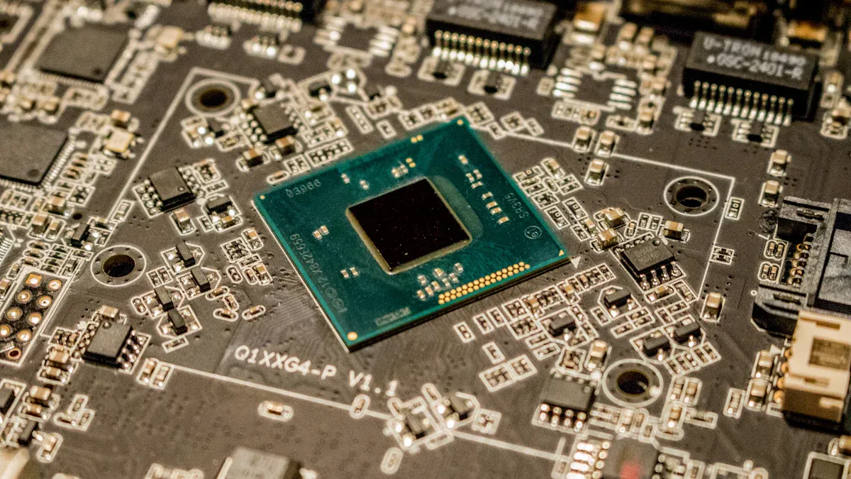
BGA Placement on SMT PCB
You use advanced pick and place machines to position the ball grid array components on the PCB. These machines, such as SMT Juki pick-and-place models, provide accuracy down to 0.01mm. You rely on automated systems to align each ball grid array with the solder paste pads. You use fiducial markers on the PCB to guide the placement process.
You minimize alignment errors by optimizing PCB design, using NSMD pads, and controlling environmental factors like temperature and humidity. You calibrate the pick and place machine regularly and check for irregularities in component dimensions. You address challenges such as solder joint reliability, component alignment, and inspection difficulties by following bga assembly instructions and using automated optical inspection.
Here is a list of common causes of misalignment and how you address them:
Equipment-related factors: You maintain and calibrate pick and place machines.
Material-related factors: You inspect component dimensions and shapes.
Process-related factors: You set correct parameters for placement.
Environmental factors: You control temperature and humidity in the assembly area.
Reflow Soldering
You move the assembled PCB into a reflow oven to melt the solder paste and create strong connections. You follow a controlled temperature profile with four main zones:
Zone | Description | Effects on Solder Joint Quality |
|---|---|---|
Preheating Zone | Gradually raises temperature to prevent thermal shock. | Prevents component warping and solder paste drying. Ideal rate: 1-3°C/s. |
Soaking Zone | Holds temperature steady for uniform heating and flux activation. | Minimizes temperature variations, ensuring consistent solder joint quality. |
Reflow Zone | Reaches peak temperature (235°C-250°C) to melt solder paste. | Forms strong metallurgical bonds; critical for optimal solder joint formation. |
Cooling Zone | Rapidly lowers temperature to solidify solder joints. | Controlled cooling prevents intermetallic compound formation, ensuring joint integrity. |
You use ramp-soak-spike or ramp-to-spike profiles to control temperature changes and reduce defects. You monitor the process to avoid issues like solder bridging, voids, and cold solder joints. You optimize solder paste application, alignment, and reflow profiles to prevent common defects such as solder balling, tombstoning, and component misalignment.
You measure key indicators of successful reflow soldering:
Indicator | Measurement Method |
|---|---|
Proper Temperature Profiling | Monitoring temperature profiles |
Solder Joint Quality | X-ray inspection |
Component Alignment | Visual inspection |
You use automated optical inspection and X-ray systems to check solder joints and component placement. You clean the area around the ball grid array with isopropyl alcohol and a brush to remove flux residue after reflow.
Note: LTPCBA uses advanced technology and strict quality control at every stage of pcba bga assembly smt pcb manufacturing. You achieve reliable results by following each step carefully and using automated inspection systems.
Inspection and Quality in PCBA BGA Assembly SMT PCB
Ball Grid Array Inspection Methods
You need to use several quality inspection methods to ensure the reliability of bga components and bga parts after soldering. Visual or optical inspection helps you spot obvious defects like misalignment or bridging. However, you cannot see the solder joints under bga parts with your eyes alone. You overcome this by using advanced tools.
Here is a table showing the most widely used inspection methods for bga components:
Inspection Method | Description |
|---|---|
Visual or Optical Inspection | You use magnification tools to find defects like misalignment or bridging on bga parts. |
Electrical Testing | You measure electrical parameters to check the integrity of bga components and detect defects. |
X-Ray Inspection | You use X-ray to see inside bga parts and find hidden defects in soldering. |
Infrared Thermography | You capture heat signatures to spot thermal issues and solder joint problems in bga components. |
Acoustic Microscopy | You use soundwaves to create images of bga parts, revealing voids or delamination. |
You often face limitations with visual inspection. You cannot check hidden solder joints under bga components. You also cannot inspect areas that are not visible, such as the center of bga parts. To solve this, you use X-ray inspection and automated optical inspection (AOI) systems.
X-ray inspection systems help you find hidden soldering defects in bga parts, such as open circuits, shorts, voids, and head-in-pillow defects.
You do not damage the board during X-ray inspection, which is important for both prototypes and production units.
Early detection of defects saves you from costly failures and reduces rework.
Tip: Always combine visual, AOI, and X-ray inspection to achieve the highest reliability in your bga assembly process.
Electrical and Functional Testing
You must test every board after soldering bga components to make sure it works as expected. You use several types of electrical and functional tests to check the performance and reliability of bga parts.
Here is a table showing the main testing methods you use for bga components:
Testing Method | Description |
|---|---|
Solder Paste Inspection (SPI) | You check the quality of solder paste before soldering bga parts to prevent future issues. |
X-ray Inspection | You inspect hidden solder joints under bga components after soldering. |
Automated Optical Inspection (AOI) | You check solder joints and placement of bga parts after soldering. |
Manual Visual Inspection | You look for defects that machines might miss on bga components. |
Flying Probe Testing | You test individual bga parts and connections for faults. |
In-Circuit Testing (ICT) | You test the electrical connections of bga components to ensure there are no faults. |
Functional Testing | You simulate real-world conditions to confirm the board with bga parts works properly. |
You use in-circuit testing to check every bga component and its connections. Functional testing lets you see if the board performs as it should in real situations. You aim for a high first-pass yield rate, which means most boards pass all tests the first time. LTPCBA achieves a 99.5% first-pass yield rate in electrical and functional testing of bga-assembled SMT PCBs.
Note: Careful testing after soldering bga components helps you deliver reliable products and avoid costly repairs.
LTPCBA Quality Assurance
You trust LTPCBA to deliver high-quality bga assembly because the company follows strict standards and uses advanced quality control processes. LTPCBA holds certifications such as ISO 9001 and IATF 16949, which ensure consistent quality and continuous improvement. The company also meets AEC-Q100 and AEC-Q200 standards for automotive reliability.
Here is a table showing the main standards and certifications LTPCBA follows:
Standard / Certification | Description | Example |
|---|---|---|
ISO 9001 | General quality management standard | Ensures consistent quality in products and services. |
IATF 16949 | Automotive quality management system | Focuses on continuous improvement and defect prevention. |
AEC-Q100 | Qualification for integrated circuits in automotive environments | Ensures reliability of ICs under automotive conditions. |
AEC-Q200 | Qualification for passive components | Ensures reliability of passive components in automotive applications. |
You also benefit from LTPCBA’s advanced quality control processes:
Quality Control Process | Description |
|---|---|
Defect Detection | You use X-ray, AOI, and electrical tests to find flawed soldering in bga parts. |
Visual and AOI Inspection | Skilled technicians and automated systems check every bga component. |
Electrical Testing | You perform ICT and functional testing to ensure proper operation of bga components. |
Advanced Quality Control Checkpoints | You use X-ray and environmental testing to validate durability and performance of bga parts. |
Documentation and Traceability | You keep digital records and track every bga component for accountability. |
Final Quality Checks | You inspect every board before shipping to ensure it meets all standards. |
LTPCBA also follows important international standards for bga assembly and SMT PCB manufacturing, such as IPC-A-610 for accepted practices, ISO for quality control, and RoHS for environmental safety.
Remember: LTPCBA’s commitment to quality inspection methods, strict standards, and advanced technology ensures you receive reliable bga components and defect-free bga parts after soldering.
You achieve reliable SMT PCB manufacturing by following each BGA assembly step. The process brings benefits like reliability, performance, thermal management, and compact design:
Benefit | Description |
|---|---|
Reliability | Strong, consistent BGA placement |
Performance | Excellent signal and power delivery |
Thermal Management | Efficient heat control |
Compact Design | Saves space on your PCB |
LTPCBA uses advanced inspection and strict standards to deliver high-quality results. You can trust their expertise for your next BGA or SMT PCB project.
FAQ
What is pcb assembly and why is it important for BGA components?
You use pcb assembly to connect electronic parts to a board. You need pcb assembly for BGA components because it creates strong, reliable connections. You achieve better performance with pcb assembly.
How does LTPCBA ensure quality in pcb assembly for BGA parts?
You trust LTPCBA for pcb assembly because you get advanced inspection and strict standards. You see X-ray, AOI, and electrical tests in every pcb assembly step. You receive reliable results from pcb assembly.
Can you use pcb assembly for prototypes and production runs?
You use pcb assembly for both prototypes and production runs. You get flexibility with pcb assembly. You order small batches or large quantities. You always receive consistent quality in pcb assembly.
See Also
Essential Strategies for Effective BGA Assembly Mastery
Understanding SMT and DIP Assembly in PCBA Processes
Common Methods and Workflow for SMT Assembly Explained
Double-Sided BGA Device Mounting Techniques for PCBA
Innovative BGA Assembly Techniques for Reliable Electronics Production