Mastering DIP Assembly and Through-Hole Tolerances
DIP assembly technology utilizes dual in-line packages to attach components onto printed circuit boards (PCBs). Through-hole tolerances assess the precision of the drilled holes, which are essential for correctly positioning the components. This process ensures reliable connections and robust soldering, ultimately guaranteeing that your PCB designs function effectively and have a long lifespan.
Key Takeaways
DIP assembly uses two-row packages to make strong board connections. It works well for both small and big projects.
Keeping exact hole sizes is important so parts fit right. This helps avoid problems during making the product.
Using proper tools and good methods in DIP assembly improves accuracy. It also makes electronics work better and last longer.
Understanding DIP Assembly Technology
What is DIP Assembly Technology?
DIP assembly technology means using dual in-line packages (DIP) to attach electronic parts to printed circuit boards (PCBs). These packages have two rows of pins that fit into matching holes on the PCB. The pins are soldered to make strong electrical connections. This method has been used for years because it is simple and dependable.
DIP assembly is great for parts needing secure connections. You can work with these parts by hand or with machines, making it useful for small or large projects. Whether you're building a prototype or producing many units, this method gives steady results.
Applications of DIP in Electronics Manufacturing
DIP assembly is important in many areas of electronics. It is used in both consumer and industrial products. Here are some common uses:
Prototyping and small-scale production: DIP parts are easy to test and replace, making them perfect for experiments.
High-reliability sectors: Industries like aerospace and military use DIP for its strength and heat resistance.
Educational tools: Many learning kits use DIP parts to teach electronics basics.
Customizable solutions: Manufacturers use DIP for special projects, especially for small orders.
As electronics grow worldwide, the need for DIP parts increases. New technologies make DIP parts even better and more precise, keeping them a trusted choice for many uses.
Advantages of DIP Assembly for Reliable PCB Connections
DIP assembly has many benefits that make it a top choice for strong PCB connections. These include:
Ease of assembly: You can insert DIP parts by hand, which is helpful for small projects.
Strong mechanical connections: The through-hole design keeps parts firmly in place, even with vibrations.
Cost-effectiveness: For small productions, DIP parts are cheaper than surface-mount technology (SMT), which needs costly tools.
Thermal and environmental tolerance: DIP parts work well in tough conditions, making them ideal for critical uses like aerospace.
Repairability: DIP parts are easy to fix or replace, saving time and money.
Using these benefits, you can create strong and lasting PCB designs. DIP assembly is still a smart choice for projects needing accuracy and durability.
The Role of Through-Hole Tolerances in PCB Design
What Are Through-Hole Tolerances?
Through-hole tolerances are the allowed size differences in PCB holes. These tolerances make sure parts fit well and stay aligned. Even small changes can cause loose parts or misaligned components. This can harm how the board works. Keeping tolerances precise helps ensure good connections and fewer problems during production.
For instance, tolerances are measured in millimeters and depend on hole size. The table below shows common tolerance ranges and their effects:
Hole Size (in mm) | Tolerance Range | Impact of Deviation | Common Applications |
|---|---|---|---|
0.2 – 0.5 | ±0.05mm to ±0.1mm | Too big: loose parts; Too small: tight fit, stress | Through-hole parts, vias |
0.5 – 1.0 | ±0.1mm | Too big: extra copper; Too small: assembly issues | High-frequency boards |
1.0 – 2.0 | ±0.2mm | Too big: short-circuit risk; Too small: misaligned parts | Power electronics, car PCBs |
Knowing these tolerances helps you design better PCBs and avoid costly mistakes.
How Tolerances Impact Component Placement and Soldering
Through-hole tolerances affect how parts are placed and soldered. If holes are too small, parts won’t fit well. This can stress pins and cause damage during soldering. If holes are too big, parts may be loose, making connections weak.
Correct tolerances are also key for soldering. Right-sized holes let solder flow evenly around pins. This creates strong connections. Wrong hole sizes can cause uneven soldering, leading to weak joints or shorts. Following accurate tolerances ensures smooth assembly and reliable results.
Common Tolerance Ranges and Their Practical Implications
Different industries need different tolerance levels. For example, car makers use tight tolerances like ±0.01778 mm for better performance. In aerospace, tolerances are crucial for safety and efficiency. Surface finishes like Ra 0.8 um reduce drag and improve reliability. These examples show how tolerances affect product quality.
The international tolerance grade (ITG) system ranks precision from IT01 (very precise) to IT16 (less precise). This system helps pick the right fit for your PCB. For high-frequency uses, tighter tolerances help control impedance and reduce losses. The table below explains more about common tolerance terms:
Parameter | Description |
|---|---|
Dk Tolerance | Shows if material suits high-frequency use; tighter is better. |
Df Value | Measures energy loss; lower values mean better performance. |
TcDk | Tracks Dk changes with temperature; high values show instability. |
Moisture Absorption | High absorption raises Dk and losses; <0.25% is ideal. |
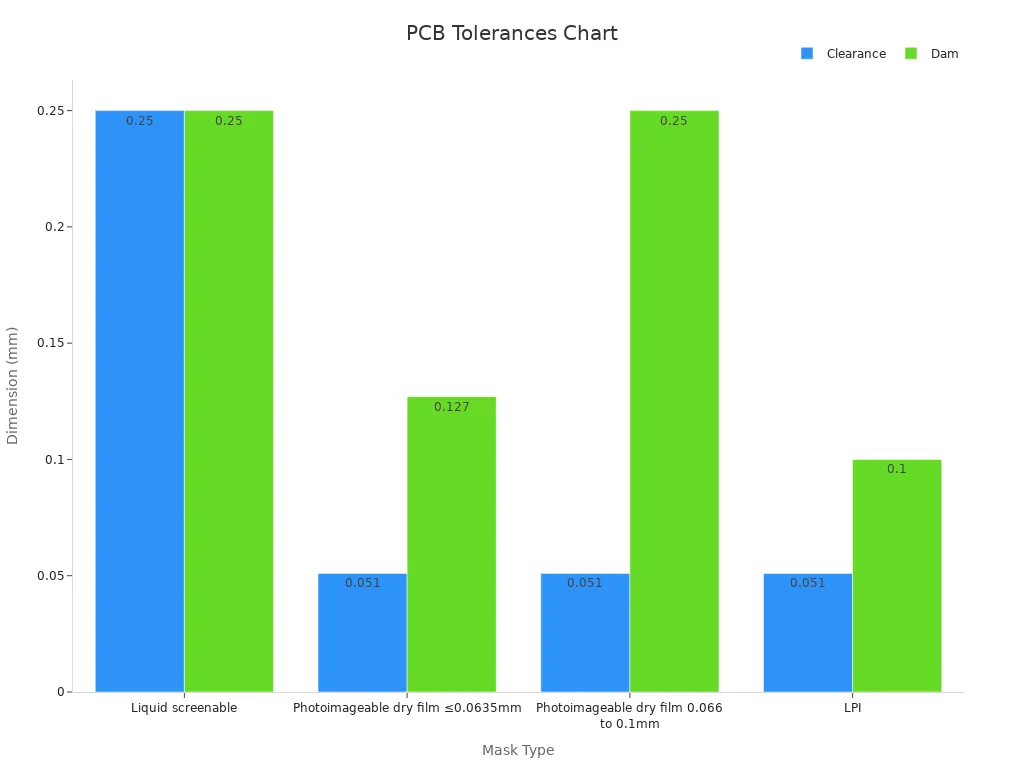
For a visual guide, the chart below shows PCB clearance and dam tolerances for different mask types:
By learning about these tolerances, you can design PCBs that meet industry needs and work well in tough conditions.
Best Practices for DIP Assembly and Through-Hole Tolerances
Ensuring Accurate Through-Hole Dimensions in PCB Design
Through-hole sizes must be correct for good PCB performance. Use exact measurements to make sure parts fit tightly. Pick PCB design software that allows detailed hole planning. Automated tools can spot mistakes early, saving time and reducing problems.
Work closely with your manufacturing team. Check designs often with experts to improve hole sizes and match production needs. Keep trace paths short and avoid crossing fast signals to reduce noise. Plan for heat control by adding thermal vias to stop overheating.
Selecting the Right Tools and Equipment for DIP Assembly
The right tools make DIP assembly easier and more accurate. Simple tools like measuring tapes and inclinometers are cheap and easy to use. For harder tasks, electronic devices and laser scanners give better results but need training. Below is a table of tools and their features:
Tool Type | Accuracy Description | Cost/Usability Description |
|---|---|---|
Metal Measuring Tapes | Cheap and simple; available in metric or English units. | |
Digital Inclinometers | Measures slopes with 0.1-degree accuracy. | Costs more than basic levels; easy to use and adjust. |
Construction Lasers | Accurate to ±1/16 inch over 100 feet. | Good for elevation checks but not small details. |
Electronic Instruments | High precision for flatness checks; needs training. | Expensive but great for critical tasks. |
Laser Scanners | Creates 3D images with high accuracy. | Very costly; best for complex designs. |
Pick tools based on your project’s needs and budget. Simple tools work for small jobs, while advanced ones suit detailed projects.
Avoiding Common Mistakes in Through-Hole PCB Design
Mistakes in PCB design can cause big problems. Use automated tools to catch errors early. Talk with your manufacturing team to make sure designs fit production limits. Place parts carefully to avoid blocking signals or causing failures.
Heat control is very important. Use thermal vias and heat sinks to keep parts cool. Too much heat can break components and shorten the PCB’s life. Choose materials that handle heat and work well electrically.
Good documentation helps avoid errors. Give manufacturers all needed files to reduce mistakes. Test your design before making many units to find problems early. This makes production smoother and more reliable.
LTPCBA’s Promise of Quality in DIP Assembly
Following Global Standards for PCB Assembly
LTPCBA ensures top-quality PCB assemblies by following global standards. These rules make sure every product is reliable and high-quality. LTPCBA follows these important IPC standards:
IPC Standard | What It Covers | Why It Matters |
|---|---|---|
IPC-A-610 | Checks quality of electronic assemblies | Ensures strong and reliable assemblies |
IPC-2221 | Guides printed board design quality | Helps create better designs |
IPC-J-STD-001 | Sets rules for soldering electrical parts | Ensures good soldering and proper assembly |
By sticking to these standards, LTPCBA makes sure your PCBs meet industry needs. They also follow IPC-7711/7721 for rework, keeping repairs accurate and consistent.
Keeping Through-Hole Tolerances Precise
LTPCBA uses advanced tools to keep through-hole tolerances accurate. This reduces errors and improves production. Automated inspections catch mistakes fast and ensure everything meets the right specs. LTPCBA also standardizes tolerances to save money without lowering quality.
Tolerance Factor | How It Affects Cost | Ways to Save Money |
|---|---|---|
Manufacturing Time | Longer time raises costs | Simplify designs, use batch production |
Material Costs | Expensive materials increase expenses | Buy in bulk, use standard materials |
Scrap Rates | Defects waste materials and time | Improve quality checks, simplify designs |
These steps help LTPCBA make affordable PCBs while keeping high standards.
How LTPCBA Makes Reliable PCBs
LTPCBA uses advanced tools and strict processes to make reliable PCBs. They use strong materials like FR-4 and aluminum, which handle heat well. Automated systems keep quality steady, and IPC-2221A rules ensure proper heat and signal control.
Metric | Value or Standard |
|---|---|
k = 220 W/m·K | |
Thermal Conductivity (FR-4) | k = 0.3 W/m·K |
IPC-2221A Temp Gradient | ΔT max = 15°C/mm |
Differential Pair Impedance | 100Ω ±10% |
Crosstalk Reduction | 40% |
By using these methods, LTPCBA creates PCBs that are reliable, efficient, and ready for modern electronics.
Learning DIP assembly and through-hole tolerances helps make precise PCBs. Following correct steps improves how well they work and last longer.
Check out LTPCBA’s top PCB assembly services. They focus on quality and new ideas to help you build strong, high-performing electronics.
Go to LTPCBA now!
FAQ
What is the best tolerance range for through-hole PCBs?
The best range depends on hole size. For a 0.5 mm hole, a tolerance of ±0.1 mm works well. This ensures parts fit and align correctly.
Can DIP assembly work in places with lots of vibration?
Yes, DIP assembly is strong and reliable. Its through-hole design keeps parts secure, even in vibrating areas like cars or airplanes.
How does LTPCBA keep through-hole tolerances accurate?
LTPCBA uses smart automated tools and strict checks. These steps make sure tolerances are exact, cutting mistakes and making PCBs more reliable.
See Also
A Comprehensive Guide to SMT and DIP Assembly Techniques
Evaluating Advantages and Disadvantages of SMD and Through-Hole Methods
Effective Strategies for Optimizing SMT Production Lines in PCBA
Essential Aspects of DIP Assembly Technology You Should Know
Important Technical Considerations for HDI PCB Surface Mounting