LED Components in PCBA: Types and Selection

LED Components are tiny parts that make light when electricity goes through them. These parts help electronics show things, signal what is happening, or light up areas. In PCBA, engineers pick LEDs to help devices work well and last longer. Picking the right LEDs can also save money and stop problems.
Key Takeaways
LED components are very important in electronics. They give light and signals. Picking the right type helps them work better and last longer.
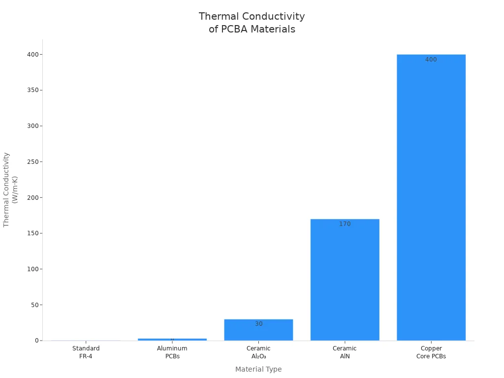
The material you choose affects how heat is handled. Aluminum and copper PCBs are best for high-power LEDs. They stop the LEDs from getting too hot.
It is important to know about electrical characteristics. Always look at voltage and current ratings. This helps keep LEDs safe when they work.
Good thermal management stops LEDs from breaking. Use the right spacing and materials to handle heat well.
EMI can mess up how LEDs work. Keep power lines and signal lines apart. This lowers interference and makes LEDs more reliable.
LED Components in PCBA
What Are LED Components
LED Components are small parts that make light when electricity flows through them. They come in many shapes and sizes. Some look like tiny chips. Others look like little bulbs. Engineers put them in devices to show signals or numbers. They also help light up screens.
Most LED Components use special materials. Many use aluminum sheets. Aluminum helps move heat away from the LED. This keeps the LED cool and working well. Making these parts means cutting and cleaning aluminum. Then, a layer is added to stop electricity from leaking. Copper paths are built for electricity to flow. Some LED Components use FR-4. FR-4 does not move heat as well as aluminum. For very strong power, ceramic materials like aluminum oxide are used. These handle heat even better.
Tip: Using good materials helps LED Components last longer and work better in devices.
Why LED Component Selection Matters
Picking the right LED Components is important for every device. The type of LED changes how much heat it makes. It also changes how bright it is and how long it lasts. If you pick the wrong LED, the device may get too hot. It might stop working early.
The LED you choose also affects the whole circuit board. The right LED can save energy. It can make the device safer. Good choices help control heat and keep the device working. This makes customers happy. Engineers also think about other parts. Resistors and capacitors help control electricity and protect the LEDs. The board material, like aluminum or FR-4, matters too. It changes how well the LED works.
Key points to remember:
The type and size of LED decide where it fits.
The board material changes how heat moves away from the LED.
Good design and space help stop overheating.
LED Components are very important for making strong and reliable electronics.
Types of LED Components
SMD LEDs
SMD LEDs are small lights that sit on the surface of a circuit board. They have a flat shape and do not need holes in the board. These LEDs give even light and last a long time. SMD LEDs work well in displays, backlights, and signs.
Feature | SMD LED | DIP LED |
|---|---|---|
Mounting and Architecture | Surface-mounted, compact design | Through-hole, larger footprint |
Light Output and Beam Angle | Broad beam angles, even lighting | Narrow beam angles, harsh hot spots |
Thermal Efficiency and Longevity | Better heat dissipation, longer lifespan | Concentrated heat, shorter lifespan |
Typical Applications | High-density applications, displays | High-vibration signage, focused indicators |
Tip: SMD LEDs are great for making thin and bright screens.
COB LEDs
COB LEDs use many tiny chips on one base. This design makes a strong, bright light. COB LEDs give smooth light without dots. They work best in flashlights, car headlights, and stage lights.
Feature | SMD LED | COB LED |
|---|---|---|
Design | Discrete components soldered to the PCB | Multiple bare dies on a single substrate |
Size | Smaller | Larger |
No. of Diodes | 1-3 | Many |
Heat Management | Dispersed across PCB | Superior via direct substrate contact |
Light Quality | Dots of light | Seamless, uniform panel |
Versatility | High (RGB mixing) | Lower (single color) |
Brightness | Bright | Very bright |
Efficiency | High | High at higher power |
Cost | Lower | Higher |
Through-Hole LEDs
Through-hole LEDs have long legs that go through the board. They are easy to solder by hand. These LEDs are strong and stay in place well. People use them in simple signs, toys, and test boards.
Advantages | Limitations |
|---|---|
Lower upfront costs | Less common in modern designs |
Easier hand soldering | Larger size |
Stronger mechanical connection | Not as good for small devices |
High-Power LEDs
High-power LEDs make very bright light. They need special boards to move heat away. These LEDs work in street lights, car lamps, and projectors. Good heat control is important for these LED Components.
Note: Boards with aluminum or copper help high-power LEDs stay cool.
Specialty LEDs
Specialty LEDs have unique uses. Some bend to fit car doors. Others let light pass through for cool building designs. Some work in 3D shapes for art or furniture. Quantum dot LEDs make colors look bright and real in TVs.
Type of LED | Application Area |
|---|---|
Flexible LED PCBs | Car dashboards and doors |
Transparent PCBs | Building lights with see-through effects |
3D Printed PCBs | Custom shapes in art and furniture |
Metal Core PCBs | Outdoor lights with strong heat control |
Quantum Dot LEDs | High-end displays with vivid colors |
Types of LED PCBs
Aluminum LED PCB
Aluminum LED PCBs have a metal base. This base helps move heat away from the LEDs. It keeps the board cool and safe. These boards are good for street lights and other lighting. Aluminum PCBs can move heat at 1.0 to 4.0 W/m·K. Some special types can go up to 8.0 W/m·K. This makes them great for strong lights.
Material | Thermal Conductivity (W/m·K) | Applications |
|---|---|---|
Aluminum MCPCB | 1.0–4.0 | Street lights, lighting |
Tip: Aluminum LED PCBs help keep LED Components cool.
Copper-Base LED PCB
Copper-base LED PCBs control heat even better than aluminum. Copper moves heat at about 390–400 W/m·K. These boards are used in high-power LED arrays. They are also used in RF power amplifiers. Copper boards can handle more heat. They last longer in hard jobs.
Great heat control for high-power LEDs
Used in spotlights and big machines
FR4 LED PCB
FR4 LED PCBs use fiberglass. They cost less and are easy to make. They do not move heat well. The thermal conductivity is about 0.25–0.3 W/m·K. FR4 boards are good for small lights and simple indicators.
Material | Cost Range (per sq. in.) | Notes |
|---|---|---|
FR4 | $0.10 - $0.50 | Good for most general applications |
FR4 boards can be made fast, sometimes in just one day.
Ceramic LED PCB
Ceramic LED PCBs use materials like aluminum oxide. They move heat very well, from 20 to 30 W/m·K. These boards are used in laser diodes and space devices. Ceramic PCBs cost more, from $2.00 to $10.00 per square inch. They also take longer to make. But they almost never fail, even in tough places.
Hybrid Substrate LED PCB
Hybrid substrate LED PCBs use more than one material. This makes them flexible and strong. They are used in advanced electronics. These boards are good when you need both strength and bending.
Benefit Type | Description |
|---|---|
Flexibility | Uses different materials to bend and fit better |
Performance | Works well for many uses |
Flexible LED PCB
Flexible LED PCBs can bend and twist easily. They are made from light materials. These boards fit in small or odd spaces. Wearable technology uses flexible PCBs. This makes devices comfy and light. In cars, flexible PCBs save space and fit in tight spots.
"Wearable technology uses flexible PCBs to make small and light devices. This helps people stay comfortable and active."
Flexible LED PCBs are also used in fitness trackers, smartwatches, and health monitors.
Key Selection Criteria for LED and LED PCBs
Picking the right LED and PCB parts helps devices work well. It also helps them last longer. Each project needs LEDs and PCBs that fit the job. Here are the main things to think about.
Electrical Characteristics
Electrical properties show how LEDs work in a circuit. Engineers check voltage and current ratings. If voltage is too low, the LED will not shine bright. Too much voltage can make the LED get hot and break. Current control is important too. Resistors or drivers stop too much current. Good grounding keeps the circuit safe. The wire size depends on how much current flows. Signal paths should keep power and signal lines apart.
Electrical Characteristic | Description |
|---|---|
Proper Grounding | Connect all LEDs to the board ground correctly. |
Wire Gauge Selection | Pick the right wire size for each section based on current. |
Signal Routing | Keep signal traces away from power traces for clean signals. |
Heat Management | Use materials like aluminum to move heat away from LEDs. |
Add resistors or drivers to stop too much current. |
Tip: Always check voltage and current before picking LED and PCB parts.
Thermal Management
LEDs make heat when they work. Good heat control stops overheating and keeps LEDs bright. Aluminum PCBs are best for strong LEDs. Thick copper spreads heat better. Thermal vias help move heat through the board. Spacing LEDs apart stops hot spots. Multi-layer boards with copper sinks cool things down.
Best Practice | Description |
|---|---|
Material Selection | Use aluminum for strong heat control. |
Copper Thickness | Thick copper lowers resistance and spreads heat. |
Thermal Via Design | Use many small vias for better heat transfer. |
LED Placement | Space LEDs to avoid heat build-up. |
Multi-layer Design | Stack layers for extra cooling. |
Thermal resistance shows how well a board moves heat. Lower numbers mean better cooling.
Dielectric Thickness | Thermal Conductivity | Thermal Resistance (Rth) |
|---|---|---|
100µm | 1 W/m·K | ≈ 1.0 K/W per cm² |
150µm | 3 W/m·K | ≈ 0.5 K/W per cm² |
<1 W/cm²: Thick FR-4 with copper planes works.
1-5 W/cm²: Use aluminum PCBs with 1-2 W/m·K dielectric.
5-15 W/cm²: Aluminum PCBs with 4+ W/m·K dielectric and thermal vias.
15 W/cm²: Copper PCBs or ceramic boards are needed.
Note: Good heat control keeps LEDs bright and stops early failure.
EMI Considerations
Electromagnetic interference (EMI) can cause problems in LED circuits. EMI comes from currents in the circuit. Shielding, grounding, and filtering help lower EMI. Grouping high-current LEDs by driver channel shortens power loops. Signal isolation keeps digital and analog parts apart. Staggering LED positions limits temperature differences.
Logical Grouping: Put high-current LEDs together by driver channel.
Signal Isolation: Keep digital and analog drivers apart.
Thermal Zoning: Stagger LED positions to control heat.
Differential Pair Routing: Keep pairs equal length and 100Ω impedance.
Power Plane Segmentation: Split analog and digital grounds.
Short Trace Priority: Keep control signals short and on inner layers.
Technique | Application Area | EMI Reduction | Implementation Notes |
|---|---|---|---|
Ferrite Beads | LED driver inputs/outputs | 30-50dB @ >10MHz | Pick 100-600Ω @ 100MHz; place <5mm from IC |
Ground Copper Pours | Signal return paths | 20dB radiated EMI | Stitch vias every λ/20; full plane under traces |
Guard Ring/Slots | Clock lines, sensitive signals | 15-25dB coupling | 1mm wide slots, grounded at both ends |
Tip: Careful layout and grounding help stop EMI problems.
Package Type and Size
The package type and size change where LEDs go and how they cool. Bigger packages have more contact area. This helps cooling. Layered PCB designs manage heat better. Thicker and wider traces help spread heat.
Bigger packages help heat move away.
Layered PCBs manage heat well.
Thick traces help in strong LED jobs.
Note: Pick package size based on space and cooling needs.
Brightness and Color
Brightness and color are important for displays and lights. SDCM (Standard Deviation Color Matching) or MacAdam ellipses are used. Most jobs use a 5-step SDCM range. Professional jobs need a 3-step range. High precision may need 1 or 2 SDCM, but differences are hard to see.
Color is measured with SDCM.
5-step SDCM is good for most jobs.
3-step SDCM is best for pro lighting.
1 or 2 SDCM is ideal for high precision.
Tip: Check SDCM ratings for color consistency in your project.
Reliability and Cost
Reliability and cost decide how well the device works and how much it costs. The Bill of Materials (BOM) is most of the cost. Brand and part availability change the price. Testing and quality checks lower the risk of failure. Accelerated Life Testing (ALT) finds weak spots and helps improve materials. ALT is important for cars and airplanes, where reliability matters most.
BOM is 65% to 80% of total cost.
Testing and quality checks are needed.
ALT helps find and fix weak points.
ALT gives quick results about possible failures and guides design improvements.
Note: Always test and check quality before picking LED and PCB parts.
Matching LED Components and PCB properties to the job is key. Do not ignore voltage ratings, heat control, or EMI checks. Careful picking makes devices work well, stay safe, and last longer.
Matching LED Components to Applications
Application Scenarios
LED components are used for many things in electronics. Engineers pick LEDs based on what each device needs. Some devices need very bright light. Others need special colors or shapes. The table below shows where LEDs are used and what they need.
Application Scenario | Specific Requirements |
|---|---|
Medical Devices | High-powered surgical and diagnostic lighting requires durability and efficient thermal management. |
Industrial and Specialty Lighting | Metal core PCBs are needed for effective heat dissipation in applications like LED grow lights and underwater lighting. |
Custom LED Boards | Design can adjust light color temperature, shape, and intensity to meet various application needs. |
Medical devices use LEDs to give clear and strong light. These devices must last a long time and stay cool. Industrial lights, like grow lights or underwater lamps, need boards that move heat away fast. Metal core PCBs help with this job. Custom LED boards let engineers change the color, shape, or brightness. This helps the board fit the job better.
Tip: Always pick the right LED type and PCB material for the job. This helps the device work well and last longer.
Environmental Factors
The place where LEDs are used can change how they work. Humidity and temperature can cause problems for PCBs and LEDs.
Water in the air can cause rust and short circuits. This makes the board not last as long.
Controlling humidity is important to stop water damage, especially in wet places.
Good protection keeps PCBs safe from water and heat changes.
Temperature changes how long a PCB can work. Each part reacts to heat in its own way.
Heat and cold can make parts grow or shrink. This can hurt the LED parts.
Different materials react to heat in different ways. This can cause problems between parts.
When materials change from heat, it can stress the board.
Engineers use coatings and seals to keep water out. They also pick materials that handle heat well. Devices in hot or wet places need extra care. Good protection keeps LEDs working and stops them from breaking early.
Note: Protecting LED boards from water and heat changes helps them last longer and work better.
Common Pitfalls in LED PCBA
Overlooking Thermal Issues
Thermal problems are a big reason why LEDs stop working in PCBA. If heat builds up, LEDs can get dim or break. Many designers forget to plan how heat will move away. This mistake can make the device not last as long. The table below lists some common heat problems and ways to fix them:
Thermal Issue | Description | Mitigation Strategies |
|---|---|---|
Thermal Resistance | How well a material blocks heat flow. | Choose materials with low thermal resistance for better heat movement. |
Thermal Stability | Ability to keep working when temperatures change. | Use materials that do not break down with heat or cold. |
Thermal Stress | Damage from parts expanding or shrinking with temperature changes. | Pick materials with similar expansion rates and design for stress relief. |
Hot Spots | Small areas that get much hotter than the rest of the board. | Use thermal imaging, place parts wisely, and add heat sinks or better power control. |
Tip: Always look for hot spots and use good materials to keep LEDs cool.
Ignoring EMI and Electrical Ratings
Electromagnetic interference, or EMI, can make LEDs flicker or stop working. Some designers do not keep power and signal lines apart. This can cause noise and make the device work badly. Not checking voltage and current ratings is also dangerous. Too much current can burn out LEDs. Too little voltage can make them dim. Good grounding and short signal paths help lower EMI.
Put high-current LEDs together.
Keep digital and analog signals apart.
Use the right resistors and drivers for safe current.
Note: Careful layout and using the right ratings keep LEDs safe.
Poor PCB Material Choices
Picking the wrong PCB material can cause lots of problems. Some boards break or lose signal quality. The dielectric constant changes how fast signals move. If it changes, signals can slow down and cause mistakes. FR-4 is cheap but can lose signals at high speeds. High dissipation factor in FR-4 means more signal loss. Even with good materials, bad design can waste their benefits.
Picking the wrong substrate can cause failures and signal problems.
Dielectric constant changes can slow signals and cause mistakes.
FR-4 can lose signals in high-speed jobs.
Not matching design to material can cause heat problems.
Tip: Match your PCB material to your LED and circuit needs for the best results.
Picking the right LED components and PCBs makes devices work well and last longer. You need to think about both how the device works and what you need in real life. The table below shows which PCB materials are good for different jobs:
Material Type | Cost Level | Best Use Case | Key Advantages |
|---|---|---|---|
Standard FR-4 | Low | Small LED boards, low-power devices | Affordable, easy to manufacture |
Polyimide / Flexible PCBs | Medium–High | Wearables, folding devices | Flexible, handles heat well |
Aluminum or Copper MCPCB | Medium | High-power, heat-intensive lighting | Great at moving heat away |
When you choose a supplier, check these things: Can they make the LED PCB you need? Do they build and test the boards themselves? Are they certified and safe? Is their team ready to help with design and quality? Do they use good and traceable materials?
Always look at datasheets and talk to trusted suppliers before you decide.
FAQ
What is the main reason to use aluminum PCBs for LEDs?
Aluminum PCBs move heat away from LEDs quickly. This helps LEDs stay cool and last longer. Aluminum also makes the board strong and safe for high-power lights.
How do I choose the right LED for my project?
Check the brightness, color, and size you need. Make sure the LED matches your voltage and current. Look at the datasheet for details. Ask your supplier if you are not sure.
Can I use FR4 PCBs for high-power LED applications?
FR4 PCBs do not handle heat well. High-power LEDs need better cooling. Use aluminum or copper PCBs for strong lights. FR4 works best for small or low-power LEDs.
Why do LEDs sometimes flicker or fail early?
Flicker often comes from poor power control or EMI. Early failure can happen if the LED gets too hot or uses the wrong voltage. Good design and quality parts help prevent these problems.
See Also
Navigating Electronic Component Sourcing for PCBA Production
Understanding PCBA: Key Components and Their Functions
Choosing the Right PCBA Supplier for Your Requirements
Essential Materials Required for Effective PCBA Manufacturing
Choosing PCB Materials for Successful SMT Assembly Processes