Key points of DIP assembly technology
DIP assembly technology is crucial in the production of electronics. It utilizes Dual In-Line Packages (DIPs), which are rectangular components with straight pins. These packages contribute to the construction of robust electronic circuits. The technology is straightforward and integrates seamlessly with circuit boards, facilitating efficient production. Standard sizes, such as 2.54 mm pin gaps and configurations ranging from 8 to 64 pins, enable precise assembly.
Key Takeaways
DIP assembly technology uses Dual In-Line Packages (DIPs) to build sturdy and dependable electronic circuits. These packages easily connect to printed circuit boards (PCBs).
Wave soldering is an important step in DIP assembly. It makes strong connections and stops rust, improving product quality and reliability.
Quality checks like Automated Optical Inspection and X-ray tests are crucial in DIP assembly. They find and fix problems early, ensuring good assemblies and saving money.
Key Components of DIP Assembly Technology
Dual In-Line Packages (DIP)
Dual In-Line Packages (DIPs) are key to DIP assembly. They have two rows of pins that connect to a printed circuit board (PCB). DIPs come in different materials, each with special features. For example:
Material Type | Features |
|---|---|
Great electrical flow, good heat control, strong build. | |
Iron-Nickel Alloy (Alloy 42) | Low heat expansion, stable in heat, less electrical flow. |
Copper-Molybdenum or Cu-W | Excellent heat control and strength for high-power uses. |
Silver or Gold Plating | Better soldering, rust protection, and electrical performance. |
The lead frame in a DIP moves heat from the chip to the PCB. Copper lead frames are great at cooling, stopping overheating, and making parts last longer. DIPs also protect the chip, keeping it safe in tough places like cars or factories. Their strong pin connections make them perfect for reliable, long-lasting use.
Printed Circuit Boards (PCBs)
Printed Circuit Boards (PCBs) are the base for DIP assembly. They hold and link electronic parts together. PCB design and materials affect how well the assembly works. For instance:
PCB Feature | Effect on Performance | Example |
|---|---|---|
Board Thickness | Thinner boards last longer under stress. | |
Pad Size | Bigger pads help assembly but may weaken joints. | Larger pads handle more bending but lower joint height. |
Pad Metallurgy | Good metal bonds are key for strong joints. | Weak bonds can cause early failures and poor connections. |
A thinner PCB, like 0.016 inches, improves joint life compared to thicker ones. Adjusting pad size and metal bonds ensures strong connections. These factors make PCBs vital for DIP assembly success.
Soldering Tools and Equipment
Soldering tools are important for strong joints in DIP assembly. Heating parts properly avoids weak solder joints that don’t work. Good soldering tools provide enough heat for proper solder flow. Key points include:
Joint strength peaks at 475–500°F for certain solders.
Solder must fully melt to reach maximum strength.
Low temperatures can create weak but good-looking joints.
Keeping the right heat during soldering ensures strong connections. Using quality solder and flux improves reliability. Whether for electronics or machines, good tools and techniques are essential for success.
The DIP Assembly Process Explained by LTPCBA
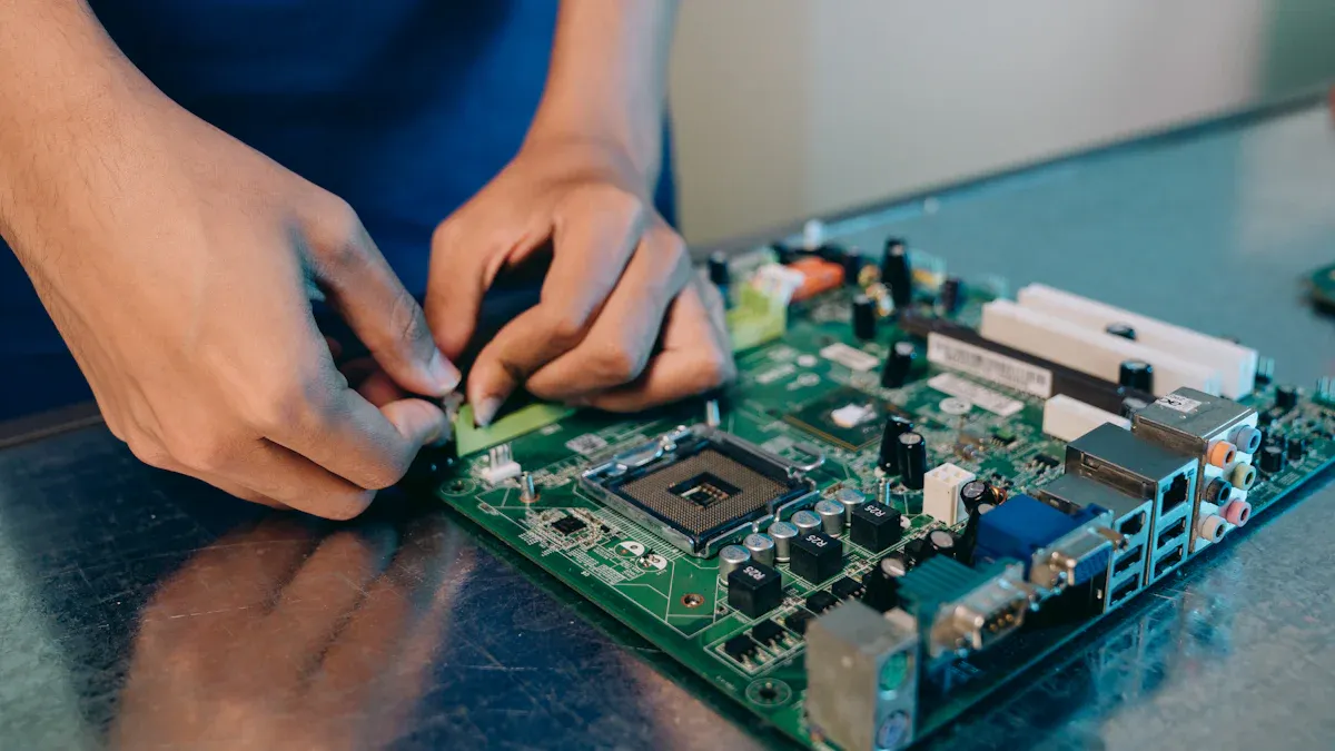
How Components Are Inserted
In DIP assembly, placing parts correctly is the first step. Parts like resistors and chips go into holes on the PCB. LTPCBA uses machines to place these parts accurately. This reduces mistakes and speeds up work.
To save time and money, LTPCBA uses C-Alley technology. This method ensures high-quality assembly at a low cost. Fully automatic machines also handle large orders quickly. These tools make the process fast and affordable.
Wave Soldering in DIP Assembly
Wave soldering is an important part of DIP assembly. The PCB passes over melted solder, making strong connections. This method is better than other soldering techniques.
Quality Feature | Wave Soldering | Other Methods |
|---|---|---|
Strong Connections | Yes | Sometimes |
High | Lower | |
Stops Oxidation | Yes (with nitrogen) | No |
Flux Control | Optimized | Less precise |
Process Control | High | Variable |
Wave soldering creates strong joints and reliable connections. Using nitrogen reduces oxidation, which weakens joints. LTPCBA carefully chooses flux and controls the process for top quality.
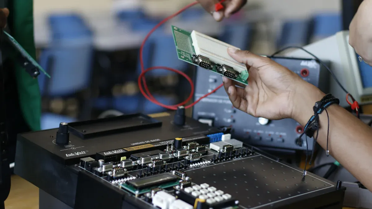
Checking for Quality
Quality checks are key to making reliable DIP assemblies. LTPCBA uses advanced methods to find and fix problems early.
Inspection Type | What It Does | Why It Helps |
|---|---|---|
Visual Check | Uses magnifiers to spot defects. | Finds solder issues, misaligned parts, and cracks early. |
Uses cameras to compare PCBs to a standard. | Speeds up production and lowers costs by catching errors early. | |
X-Ray Check | Finds hidden problems in multi-layer boards. | Spots solder and internal issues for better reliability. |
In-Circuit Testing | Tests parts and circuit paths quickly. | Ensures all parts work before final testing, reducing errors. |
Functional Testing | Confirms the PCB works as designed. | Makes sure the final product meets its purpose. |
By using these checks, LTPCBA ensures every PCB is high quality. Automated and X-Ray checks find hidden problems, while functional tests confirm the product works perfectly.
Advantages of DIP Assembly Technology
Simple and Easy to Use
DIP assembly is known for being simple to use. Its basic design makes manufacturing easy and keeps costs low. DIP parts work well with through-hole mounting, making assembly simple. You can use manual or automated methods for this process. The design also helps manage heat, keeping circuits reliable.
Metric | Description |
|---|---|
Simplicity | DIP's basic design is easy to make and saves money. |
Assembly Process | Works with through-hole mounting for manual or machine assembly. |
Heat Management | Handles heat well, making circuits last longer. |
Component Replacement | Easy to swap parts without harming nearby components. |
Soldering Ease | Simple to solder, fitting many assembly methods. |
This simplicity makes DIP great for testing and prototyping. You can replace parts easily without damaging other components.
Affordable for Production
DIP assembly is cost-effective, especially for large-scale production. Its simple design lowers manufacturing costs. Dip coating, a common method, keeps costs low while ensuring quality.
A McKinsey study shows lean methods can cut costs by 25-30%.
Automated processes reduce labor costs, making DIP affordable for big projects.
These features make DIP assembly a smart choice for balancing cost and quality.
Reliable and Long-Lasting
DIP assembly creates strong and durable components. The sturdy design ensures pins stay connected over time. Good heat control stops circuits from overheating, making them last longer.
DIP parts work well in tough places like factories or cars. Their strong build protects chips from damage, keeping them working. This reliability makes DIP assembly a trusted option for dependable electronics.
Challenges in DIP Assembly Technology
Manual Labor Needs
DIP assembly often depends on people to place parts. This process is slower than automated methods like SMT. Placing parts by hand needs skill and care, which raises costs. It also increases the chance of mistakes. For small projects or testing, this method works fine. But making large amounts can be hard due to time and workers needed.
To fix this, semi-automatic tools can help speed things up. These tools lower mistakes but still allow manual control. Even so, needing people for the work is a big problem for making large quantities.
Limits on Small Sizes
DIP parts are bigger than newer surface-mount parts. This makes them hard to use in tiny devices where space matters. For things like smartphones or smartwatches, DIP assembly might not work. The size and pin spacing of DIP parts make miniaturization tough.
Still, DIP parts are great for uses where size doesn’t matter much. For example, they’re used in factory machines and older systems. Their strong build and easy handling make them perfect for these jobs.
Challenges with Modern Devices
DIP assembly struggles with today’s fast electronics. DIP parts are slower, so they don’t work well for quick data tasks. But they are strong and handle heat well. They’re good for bumpy places like cars and airplanes. Their simple design also makes fixing and testing easy, which is helpful for older systems.
DIP technology is still useful in areas where strength and reliability are more important than size. It remains a key part of industrial and research electronics, showing its lasting value.
Best Practices for DIP Assembly by LTPCBA
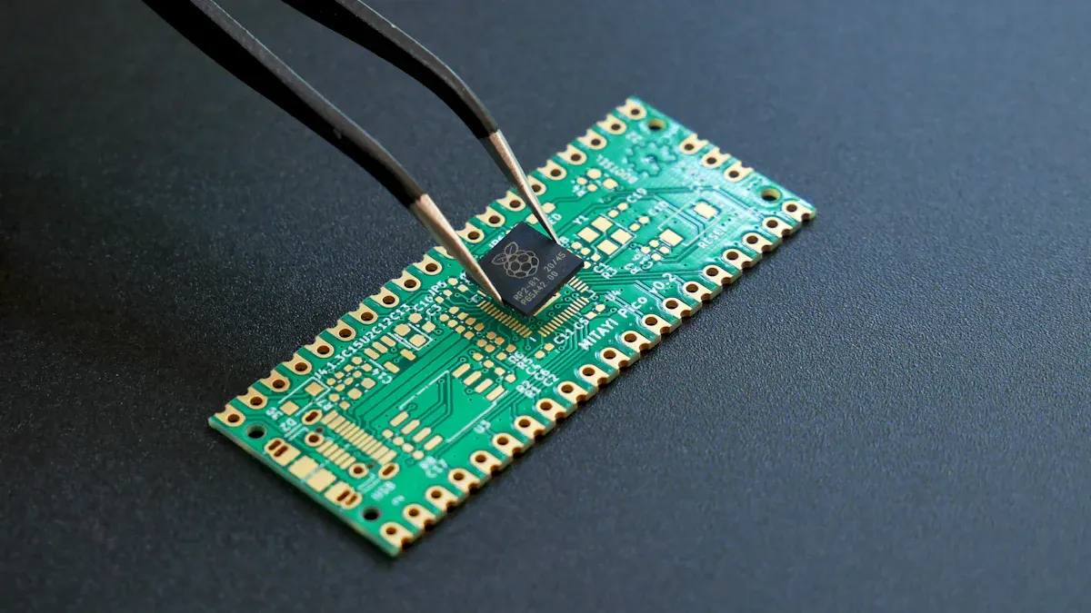
Ensuring Accurate Component Placement
Placing parts correctly is very important in DIP assembly. Each part must fit perfectly into the PCB holes. If parts are not aligned, circuits may fail or connections may weaken. LTPCBA uses special machines to place parts accurately. These machines make assembly faster and reduce mistakes.
Follow rules like IPC-A-610 for best results. This rulebook explains how to place parts and solder them properly. Sticking to these rules helps create high-quality assemblies.
Using High-Quality Soldering Materials
Good soldering materials make assemblies strong and reliable. High-quality solder creates solid joints and lowers the chance of problems. LTPCBA uses safe materials that meet strict rules like RoHS standards.
Tests check if soldering materials work well:
Test Type | What It Checks | Passing Score |
|---|---|---|
Edge Dip Test | Measures how well solder sticks | At least 95% wetting |
Wave Solder Test | Tests soldering in waves | No visible defects |
Wetting Balance Test | Checks solderability with numbers | At least 95% wetting |
MIL-STD-883 Method 2003 | Full solderability test | 95% coverage, under 5% flaws |
Using good solder and flux makes joints stronger and last longer.
Implementing Advanced Inspection Protocols
Checking for mistakes is key to keeping DIP assembly quality high. LTPCBA uses smart tools to find problems early. Automated Optical Inspection (AOI) and X-ray tests are very helpful. They spot issues like misplaced parts or hidden solder flaws.
Metric | Result |
|---|---|
Problem Detection Rate | |
Wrong Judgment Rate | Less than 10% |
Time Per Inspection | 7 seconds |
Efficiency Boost | Over 30% |
These methods ensure every assembly is top quality. They also save money by reducing the need to fix errors later.
DIP assembly is important for making electronics. It is simple, affordable, and dependable, which makes it popular in many industries. The market for Dual In-line Packages is growing fast. In 2023, it was worth $1.5 billion, and it’s expected to grow by 7.20% each year until 2033. LTPCBA can help improve your production. Their modern tools and careful quality checks make assembly quick and reliable.
FAQ
What is the main purpose of DIP assembly technology?
DIP assembly links parts to PCBs using through-hole mounting. It makes strong connections, keeping circuits reliable and long-lasting for many uses.
How does wave soldering improve DIP assembly?
Wave soldering makes strong joints by flowing melted solder on PCBs. It stops oxidation and keeps quality steady in large-scale production.
Why is accurate component placement important in DIP assembly?
Correct placement avoids misaligned parts and weak connections. It helps circuits work properly and lowers the chance of mistakes.
See Also
Understanding SMT And DIP Assembly For PCBA Needs
Key Considerations For HDI PCB Surface Mount Assembly
Enhancing Project Efficiency With Quick-Turn PCB Prototypes
Evaluating Ordinary Versus Online AOI For SMT Assembly
Defining Full Turn-Key PCB Manufacturing And Assembly Process