Key points for controlling process parameters of SMT wave soldering
You get the same good quality in smt wave soldering by watching every step. Research shows that better wave soldering settings can lower defect costs fast and make pcb results better. LTPCBA’s new technology and strict rules help you control temperature, pcb assembly steps, and smt soldering process changes for strong soldering results.
Key Takeaways
Control important wave soldering steps like putting on flux, preheating, solder temperature, conveyor speed, wave height, and cooling. This helps make strong and clean solder joints.
Use sensors and smart machines to watch temperatures, speeds, and wave height all the time. This helps find problems early and keeps the quality the same.
Follow strict quality rules and do checks like AOI and SPC. This stops defects like bridging and makes sure every PCB works well and lasts a long time.
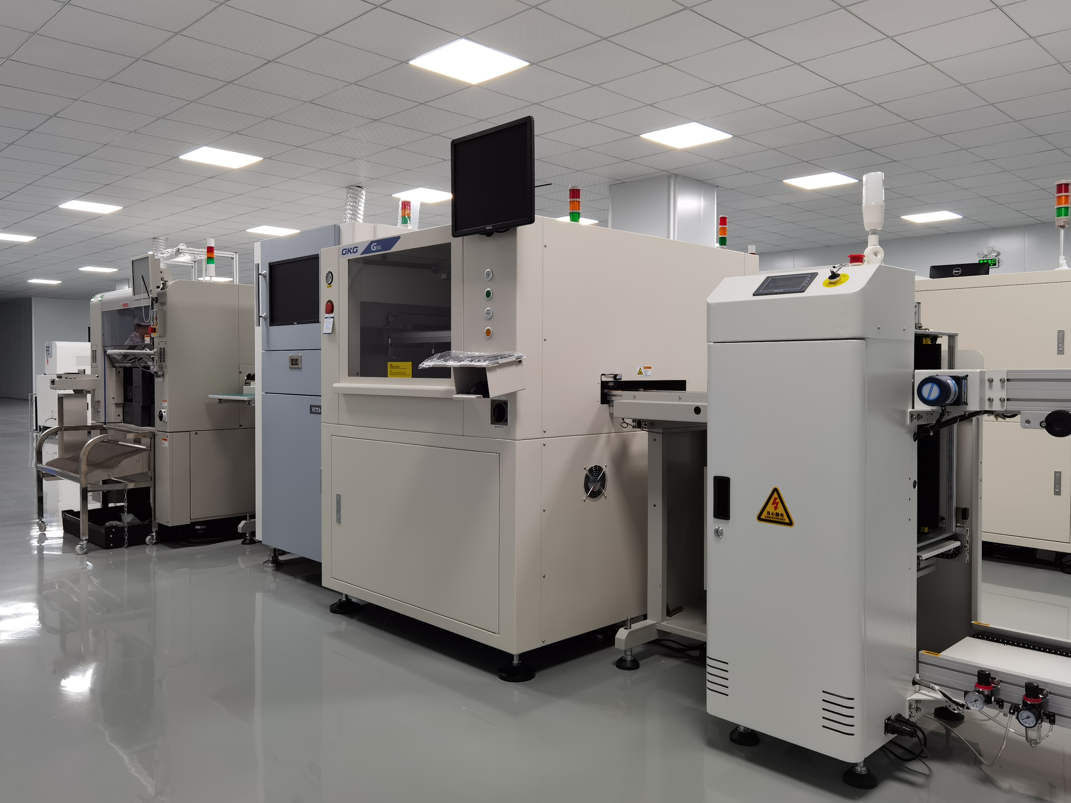
SMT Wave Soldering Overview
Process Steps
First, you get your pcb and parts ready for smt wave soldering. You put the pcb on a moving belt called a conveyor. The conveyor takes the pcb through different steps. At the start, you put flux on the pcb. Flux helps clean and get the surfaces ready for soldering. Then, the pcb goes into the preheating area. In this area, the pcb gets warmer so it does not get damaged by heat later. After preheating, the pcb moves over the wave soldering machine. Hot liquid solder makes a wave that touches the bottom of the pcb. This step makes strong solder joints. Next, the pcb goes to the cooling area. Cooling makes the solder hard and keeps the parts in place. You need to be careful at every step to make sure the soldering is good.
Key Parameters
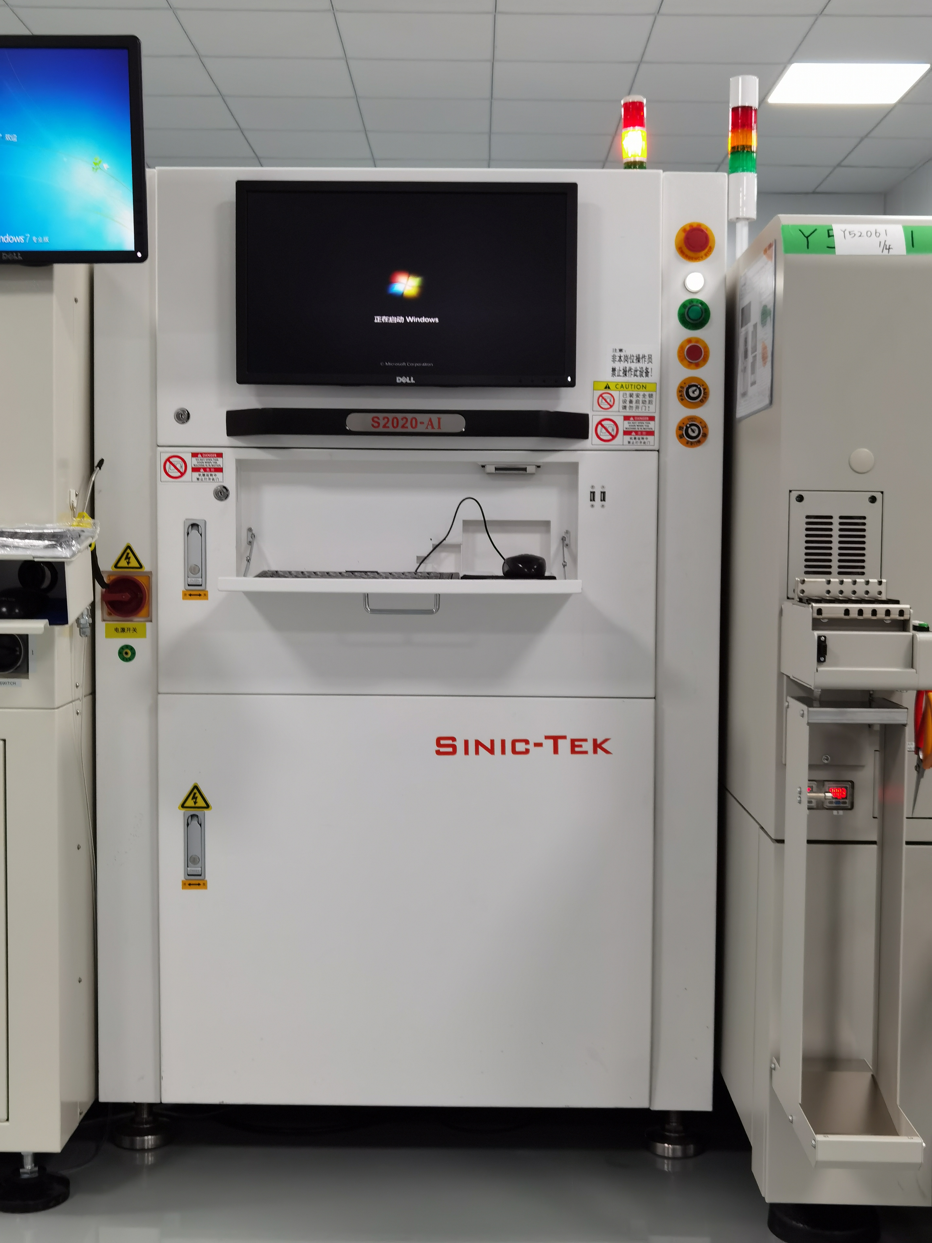
You have to watch many things during wave soldering. These things are flux application, preheating temperature, solder temperature, conveyor speed, wave height, and contact time. Each one changes how well the soldering works and how the pcb turns out. You should check these things often. LTPCBA uses special machines to keep the process steady and safe. You also need to think about the pcb material and where you put the parts. These things help stop problems and make the soldering better. If you pay attention to these key things, you can get great soldering results every time.
Tip: Always check your process steps before you start a new batch. This helps you find problems early and keep your pcb quality the same.
Flux Application
Importance
It is important to watch how you use flux during soldering. Flux gets the surfaces ready by cleaning off oxides. It also helps the solder move and stick better. Using the right flux can stop problems like bridging and weak joints. Tests show that picking good flux gives better results. For example:
Engineers tried nine kinds of flux in wave soldering. They took out five because they left dirt and residue. The last four were tested for insulation and how clean they were. Only three passed, and the best one had just three defects on hard boards. This shows that good flux makes soldering better and lowers bridging.
Another test looked at how flux is put on. Engineers changed spray speed, amount, and air knife pressure. They found the best way to cover the board evenly. These changes made soldering better and stopped problems like bridging.
When you pick the right flux and use it well, soldering is more reliable. You also have fewer problems like bridging and other defects.
Control Methods
You can control how you use flux by following some steps. First, always pick the right flux for your process. Next, set the spray speed and amount for your board size. Change the air knife pressure to spread the flux evenly. Check the coverage with special paper or tools. If you see gaps or too much flux, change your settings. Good control of flux use helps stop bridging and makes strong joints. LTPCBA uses smart machines to keep these steps steady, so you get good results every time.
Preheating
Temperature
You need to watch the temperature during preheating. The right heat helps the flux work and gets the PCB ready. If it is too hot, the board can get hurt or have shorts. If it is too cold, the flux might not work well. You could see skips or leftover stuff on the board. Always check the heat before you start a new batch. LTPCBA uses special tools to watch the heat at every step. This makes sure each PCB gets the right amount of heat. You can use sensors to see the heat in real time. Keeping the heat steady helps stop problems. Always follow what the flux maker says about heat. If you see soldering problems, check your heat settings first.
Tip: Use a chart to write down the heat at different spots on the PCB. This helps you find hot or cold spots fast.
Time
You also need to watch how long the PCB stays in preheating. Time and heat work together to get the board ready. If the board stays too long, it can get too hot and have shorts. If it is too short, the flux may not work and you can get bad joints. There are no strict rules for preheating time. You must change it based on the flux and PCB type. Always test your steps when you use new stuff. LTPCBA says to check both heat and time for each run. This helps you stop problems and keep your soldering steady.
Solder Temperature
Setting
You need to pick the right soldering temperature for strong joints. The right heat helps the solder melt and stick to metal pads. If the temperature is too low, the solder will not melt all the way. This can make weak joints or bad connections. If the temperature is too high, you might hurt the PCB or parts. You could also get solder bridges or burnt spots.
To choose the best temperature, look at your solder type. Lead-free solder needs more heat than leaded solder. Most lead-free solder works best between 250°C and 270°C. Leaded solder needs less heat, about 230°C to 250°C. Always use the temperature the solder maker suggests.
Tip: Write down your soldering temperature for each project. This helps you keep your work steady and get good results again.
Monitoring
You have to watch the soldering temperature the whole time. The heat can change as the machine works. If the temperature drops, soldering may not work well. If it gets too hot, you can damage the board or parts. Use sensors to check the heat at the solder wave. Many new machines show the temperature on a screen. You can set alarms if the heat goes out of range.
Check the temperature before you start each batch. Watch the heat during soldering to find problems early. If you see changes, stop and fix them before you keep going. Good watching helps you avoid problems and keeps your soldering good.
Note: LTPCBA uses special tools to watch soldering temperature. This helps you get the same good results every time.
Conveyor Speed
Optimization
You control conveyor speed to manage how long each PCB stays in the solder wave. This step shapes the flow of your entire process. When you set the right speed, you help the solder flow reach every joint. You want the flow to cover all pads without missing any spots. If you move the conveyor too fast, the flow does not have enough time to make strong joints. If you move it too slow, the flow can cause too much heat and damage the board. You should group PCBs with similar needs and test different speeds. This helps you find the best flow for each batch. LTPCBA uses advanced machines to keep the flow steady and accurate. You can use sensors to watch the flow and adjust the speed in real time. Always check the flow before you start a new run. Good flow control means fewer defects and better soldering.
Impact
Conveyor speed changes the flow of solder and the quality of your joints. The flow must match the needs of your PCB and parts. If you set the speed wrong, you see problems in the flow and in the finished board. Here are some common issues linked to conveyor speed and flow:
Fast conveyor speed makes the flow too short, causing incomplete soldering.
Slow conveyor speed lets the flow last too long, leading to over-soldering and board discoloration.
Wrong flow can cause bridging, cold joints, or not enough solder.
Wave soldering profiling shows that conveyor speed is a key factor in flow and solder yield. You must control the flow with the right speed, preheat, and immersion depth. When you set the flow just right, you lower defect rates and get strong, clean joints. Always watch the flow during production to keep your quality high.
Wave Soldering Parameters
When you set up wave soldering, you must control key parameters to get strong and clean soldering results. The two most important parameters are wave height and contact time. These settings affect how well the soldering works and how the solder covers the board.
Wave Height
Wave height is the distance the solder wave rises above the solder pot. You need to set this height so the solder touches all the pads and leads. If the wave is too low, some parts will not get enough soldering. If the wave is too high, solder can splash or bridge between channels. Most wave soldering machines let you adjust the wave height with simple controls. LTPCBA uses advanced wave soldering machines that keep the wave height steady. You can check the wave height by looking at the soldering line on the board. Good wave height helps the solder flow into all channels and makes sure every joint gets enough soldering.
Tip: Always check the wave height before you start a new batch. This step helps you avoid missing joints or extra soldering.
Contact Time
Contact time is how long the board stays in the solder wave. You want enough time for the solder to cover every joint, but not so long that you damage the board. Most wave soldering machines let you set the contact time with the conveyor speed. LTPCBA uses machines that keep the contact time steady for every board. If the contact time is too short, you get weak soldering. If it is too long, you can overheat the board or cause bridges between channels. You should test different contact times to find the best setting for your boards.
Note: Good control of wave soldering parameters helps you get strong, clean soldering every time.
Cooling Control
Rate
You need to watch how fast the board cools after wave soldering. The cooling rate changes how the solder joints form. It also changes how the board’s temperature drops. If you cool the board too fast, the temperature can drop quickly. This can put stress on the solder joints. Stress can cause cracks or weak spots. If you cool the board too slowly, the board stays hot for too long. This can make the solder joints look dull or rough. You want the temperature to drop at a steady speed. This helps make strong and shiny solder joints. Most experts say to cool the board at 3°C to 6°C each second. You should check the temperature at different places on the board. This helps you make sure the cooling rate is even.
Tip: Use a chart to write down how fast the board cools. This helps you see if the temperature drops too fast or too slow.
Methods
There are a few ways to control the board’s temperature during cooling. Forced air cooling is used a lot. You blow cool air over the board to lower the temperature. Some lines use water-cooled plates or special tunnels to cool the board. You should put sensors in important spots to watch the temperature. Change the airflow or cooling power if the temperature changes too fast or too slow. Always keep the temperature drop steady to stop defects. LTPCBA uses smart machines to watch and control the temperature during cooling. This makes sure every board leaves with the right temperature and strong solder joints.
Note: Good cooling control helps you stop stress and defects from sudden temperature changes.
PCB and Components
Placement
It is important to think about where you put parts on your pcb. Good placement helps stop mistakes and makes building easier. Start by putting connectors in their spots first. After that, place other surface mount components by what they do and how much heat they make. Try to keep all surface mount components on one side of the pcb. This makes building faster and helps avoid errors. Make sure each part faces the same way. This helps with checking and soldering.
Here are some things to remember for better placement:
Put circuits with the same job and voltage together to make wiring easy.
Keep analog and digital circuits apart to stop signal problems.
Place fast and sensitive parts away from the edges to lower EMI.
Put surge suppressors close to input connectors and do not use vias in their paths.
Use fewer sockets to help signals stay strong.
Make footprints better for heat, like using thermal pads under ICs.
Place parts in a way that makes building quick and simple.
Plan via size and where you put them for fast circuits.
Always check your parts before you finish your pcb layout.
Check every step of placement to make sure solder joints are strong and the board works well.
Material
You need to pick the right pcb material for your project. The material changes how your pcb deals with heat, shaking, and signals. Some industries, like aerospace, have strict rules for pcb materials. These materials must handle shaking, heat changes, and follow safety rules. High-temperature laminates and copper plating help your pcb last longer and deal with heat better.
Here is a table with common pcb materials and what to think about:
PCB Material Type | Key Properties & Performance Metrics | Application Suitability & Industry Validation |
|---|---|---|
FR-4 | Dielectric constant about 4.2; strong; Tg: 130-180°C; not expensive | Used in most electronics; good balance of cost and performance |
Polyimide (High-temp) | Tg: 280-350°C; low CTE; strong against chemicals | Best for high-temp and high-frequency uses; does not warp easily |
Ceramic-Based Substrates | High thermal conductivity; low CTE | Great for high-frequency and high-temp uses; helps stop overheating |
Rogers | High dielectric constant; low water absorption; good at moving heat | Used in RF, cars, and aerospace; good for fast and hot uses |
When you pick materials, think about the electrical, heat, and strength needs of your pcb. Look at all the parts and where you put them to match your design goals. Good choices in material and placement help your pcb work better and have fewer problems.
Troubleshooting
Common Defects
You may see several common defects during the soldering process. Bridging stands out as one of the most frequent issues. This defect happens when solder connects two pads or leads that should stay separate. Bridging can cause short circuits and damage your board. You might also find voids in the solder joints. Solder voids form when trapped gases or flux do not escape during the soldering process. These voids weaken the joint and lower reliability. Other defects include cold joints, insufficient solder, and component misalignment. Each defect can lead to poor performance or even failure of your PCB. You need to watch for these problems at every stage.
Solutions
You can prevent bridging by adjusting the wave height and contact time. Make sure you use the right amount of flux and check the conveyor speed. If you see solder voids, try changing the preheating temperature or flux type. Good control of the soldering process helps you avoid most defects. Use automated inspection tools to catch defects early. Clean your equipment often to stop bridging and other issues. Train your team to spot defects quickly. Keep records of each batch to track when and where defects appear. This approach lets you fix problems before they affect your final product.
Tip: Always review your soldering process after each run. Quick action on defects keeps your production line strong and reliable.
Quality Assurance at LTPCBA
Standards
You want every pcb to be high quality. LTPCBA follows strict rules for wave soldering. The company has special certifications that show it cares about quality. These certifications cover each step, from picking materials to checking the finished board. You can see how LTPCBA’s rules help make strong soldering and good pcbs in the table below:
Certification / Metric | Purpose / What It Proves / How It Helps Production |
|---|---|
ISO 9001 | Makes sure the company uses good processes and keeps customers happy. |
ISO 14001 | Shows the company uses eco-friendly ways to make things. |
RoHS | Limits bad chemicals to help the environment. |
CE Marking | Proves the company follows EU safety and green rules. |
UL Certification | Shows the product is safe and works well, even for cars. |
These rules help stop defects and keep your pcb safe during wave soldering. You get the same good soldering because LTPCBA uses these rules every time.
Monitoring
You need good monitoring to keep your process safe. LTPCBA uses smart tools to watch every step of wave soldering. The company uses SPC to find problems early. AOI checks each pcb for mistakes right after soldering. You also get ICT and FCT to make sure every pcb works right. LTPCBA checks FPY to see how many boards pass the first time. The team uses X-ray Solder Joint Analysis to find hidden problems in solder joints. Every step gets checked and written down.
AOI finds mistakes early.
ICT and FCT make sure pcbs work and are safe.
SPC and FPY help lower waste and make soldering better.
X-ray checks solder joints after soldering.
Real-time monitoring with IoT and AI keeps things steady.
You get good results because LTPCBA’s monitoring stops problems before they reach you. This way, you get strong soldering and good pcbs every time.
You get the best SMT wave soldering by watching each step.
You look at data to change wave height, speed, and heat.
You use your eyes, machines, and SPC to find problems early.
LTPCBA’s smart tools and help let you make strong, good PCBs every time.
FAQ
What is the best way to prevent solder bridging during wave soldering?
You should control wave height, contact time, and flux amount. Use AOI to check for bridging after soldering.
How do you choose the right preheating temperature?
You follow the flux manufacturer’s guidelines. Use sensors to monitor the board. Adjust temperature based on your PCB and component needs.
Why does conveyor speed matter in wave soldering?
Conveyor speed controls solder contact time.
You get strong joints and fewer defects by setting the right speed for your board.