High TG PCB IPC-3 Class Quality Standards
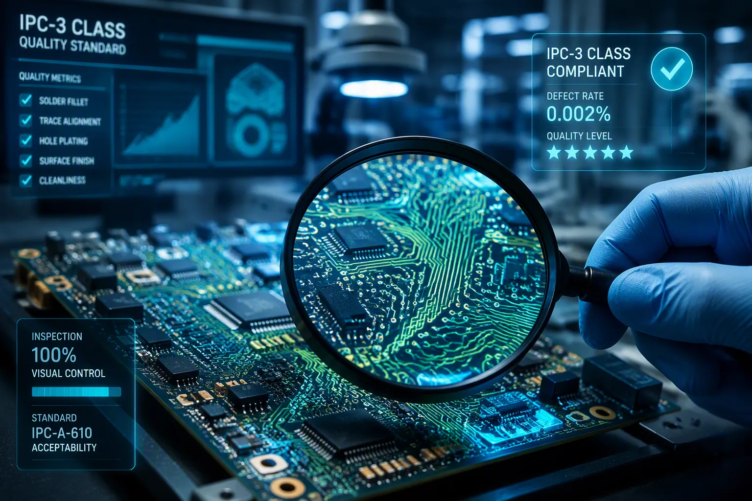
When you design boards for systems where failure is not an option, you cannot accept any defects. The IPC-6012 Class 3 standard sets the highest reliability bar for High TG PCB manufacturing. These boards must handle extreme heat without breaking apart or losing electrical function.
You need materials with a glass transition temperature above 170°C and thermal conductivity over 0.4 W/m·K, per IPC-4101. Your supplier must pass tough tests: DSC, TMA, TGA, T260/T288/T300, and solder float. Checks on size accuracy, cross-section views, and ionic cleanliness verify every board.
Military, aerospace, and medical devices require these standards. One flaw can cost lives. You must confirm your High TG PCB meets every Class 3 rule before use.
Key Takeaways
Pick laminates that have a glass transition temperature above 170°C and thermal conductivity higher than 0.4 W/m·K.
Pass thermal tests like DSC, TMA, TGA, T260/T288, and solder float to prove heat resistance.
Follow strict size limits, including bow and twist under 0.75% and annular rings of 2 mil on external layers.
Make sure barrel fill is 75% for plated through-holes and plating thickness is over 25µm to avoid cracks.
Work with a certified IPC-6012 Class 3 maker that does strict checks and thermal cycling tests.
High TG PCB Material Specifications for IPC-3 Class
Selecting the right laminate material is the base for any High TG PCB that must meet IPC-6012 Class 3 rules. You can't just pick any high-temperature board material and expect it to work. The IPC-4101 standard has specific slash sheets that set the lowest performance limits. For example, slash sheet /24 needs a minimum Tg of 175°C, and slash sheet /26 sets the lowest limit at 170°C. These rules make sure your board can handle the heat from lead-free assembly and tough operating conditions.
IPC-4101 Laminate Requirements and Tg Threshold
The glass transition temperature, or Tg, is the point where a laminate changes from a hard, glassy state to a soft, flexible state. Below this temperature, the material keeps its strength and shape. Above it, the resin matrix softens and expands quickly. For IPC-3 Class compliance, you need a laminate with a Tg of at least 170°C. Standard FR-4 materials with Tg around 130°C cannot handle the heat stress that military, aerospace, or medical uses put on them.
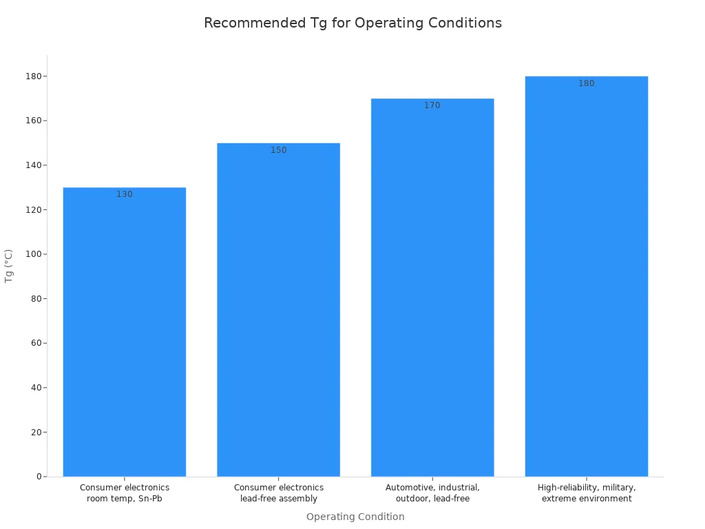
Your operating conditions decide which Tg level you need. Consumer electronics with tin-lead assembly might only need Tg values of 130°C or higher. Lead-free assembly processes need more, pushing requirements to 150°C or above. Automotive, industrial, and outdoor uses with lead-free assembly need a minimum of 170°C. For high-reliability military or extreme environment uses, you should aim for Tg values of 180°C or higher. The table below shows these recommendations:
Operating Condition | Recommended Tg | Typical Material Grade |
|---|---|---|
Consumer electronics, room temperature operation, Sn-Pb assembly | Tg ≥ 130°C | Standard FR4 (e.g., Shengyi S1141) |
Consumer electronics with lead-free assembly | Tg ≥ 150°C | Mid-Tg FR4 (e.g., Shengyi S1150G) |
Automotive, industrial, or outdoor operation with lead-free assembly | Tg ≥ 170°C | High Tg FR4 (e.g., Shengyi S1170) |
High-reliability, military, or extreme environment applications | Tg ≥ 180°C | High Tg FR4 (e.g., ITEQ IT-180A) |
You must leave a 20°C to 25°C gap between the laminate Tg and the highest processing or operating temperatures. High temperature exposure makes the matrix break down without this safety margin. High thermal stress in dense layouts hurts mechanical stability over time.
Key Properties: Thermal Conductivity, CTE, and Decomposition Temperature
Beyond Tg, you must check several other important properties. Thermal conductivity measures how well your board gets rid of heat. IPC-4101 requires values above 0.4 W/m·K for Class 3 uses. Higher thermal conductivity stops hot spots that can hurt performance over time.
The coefficient of thermal expansion, or CTE, tells how much the material grows when heated. High-Tg FR4 materials have lower CTE values above Tg, so they resist shape changes better than standard laminates. This property directly affects your board's ability to keep exact alignment during temperature changes.
Decomposition temperature, or Td, shows when the resin matrix starts to break down chemically. You want a Td of 340°C or higher to give the biggest safety margin for lead-free assembly. Also, check T260 and T288 values, which measure how many minutes the material can handle 260°C or 288°C before it separates. For good lead-free compatibility, look for T260 over 30 minutes and T288 over 15 minutes.
High-Tg materials also fight conductive anodic filament (CAF) formation by absorbing less moisture, usually 0.10-0.12% compared to 0.15% for standard FR-4. This better moisture resistance lowers the risk of delamination and improves shape stability. You also get better flexural strength at high temperatures, which reduces board cracking during mechanical stress. These performance features make high-Tg laminates a must for any High TG PCB meant for mission-critical uses.
Thermal Testing for IPC-3 Class Certification
Thermal testing proves your High TG PCB can survive real-world heat stress. These tests simulate the harsh conditions your board will face during assembly and operation. Without them, you cannot verify that your materials and manufacturing processes meet IPC-3 Class requirements.
High TG PCB Thermal Analysis Methods: DSC, TMA, TGA
Differential scanning calorimetry (DSC) measures your laminate's glass transition temperature. You heat a small sample alongside a reference material. The instrument detects the heat flow difference between them. When your sample reaches Tg, it absorbs more heat as the resin transitions from glassy to rubbery state. For IPC-3 Class compliance, your DSC curve must show a clear Tg above 170°C.
Thermomechanical analysis (TMA) measures dimensional changes as temperature rises. You place a probe on your sample and heat it at a controlled rate. The probe tracks expansion. Below Tg, expansion stays low. Above Tg, the material expands rapidly. TMA gives you the coefficient of thermal expansion (CTE) values. You want a low CTE below Tg, typically under 50 ppm/°C, to prevent warping and stress on plated vias.
Thermogravimetric analysis (TGA) measures weight loss during heating. You suspend a sample on a precision balance inside a furnace. As temperature climbs, the resin decomposes and releases gases. The weight loss curve reveals your decomposition temperature (Td). For lead-free assembly compatibility, you need a Td of 340°C or higher. This ensures your laminate won't break down during multiple reflow cycles.
Parameter | IPC Class 2 | IPC Class 3 |
|---|---|---|
Temperature cycling range | -40°C to +85°C | -55°C to +125°C |
Thermal stress testing | Standard requirements | Stricter requirements per IPC-6012 section 3.9 |
Glass transition temperature (Tg) of laminate | Standard Tg | Higher Tg required for extreme temperature exposure |
Environmental stress screening | Standard | More rigorous, including extended cycling, vibration, and humidity cycling per IPC-TM-650 |
IPC-6012 section 3.9 explicitly requires enhanced thermal management considerations for Class 3 boards, including stricter requirements for thermal stress testing compared to Class 2.
T260/T288/T300 and Solder Float Test Procedures
The T260 test follows IPC-TM-650 Method 2.4.24.1. You raise a test sample's temperature at 10°C/min until reaching 260°C, then hold it there. A sensor detects the onset of delamination, cracking, moisture release, or other material events. The time from dwell start to the detected event is your time to delamination. For high Tg materials, you need a minimum of 30 minutes at 260°C.
The T288 and T300 tests work the same way but at higher temperatures. These tests simulate the extreme heat of lead-free soldering. They reveal weak resin-to-glass bonds that might fail during assembly. Your material should survive longer at T288 than at T300, since higher temperatures accelerate decomposition.
The solder float test creates a steep temperature gradient from the solder-contact face into the laminate. Copper and the resin-glass system expand differently, so marginal barrel plating, corner geometry, internal-layer connections, and laminate interfaces can open or separate. You float your test coupon on molten solder at 288±5°C for 10 seconds per IPC-TM-650 Method 2.6.8E. Then you examine microsections for defects.
Barrel copper must remain continuous.
Copper-to-inner-layer connections must remain intact.
Lands and foil must remain attached without prohibited lifting or cracking.
Laminate must remain free from prohibited blistering, delamination, or other heat damage.
You can also enhance thermal performance through design choices. Incorporate thermal vias, copper coins, or embedded heat spreaders in your PCB design. Use advanced thermal interface materials with higher thermal conductivity. Implement active cooling solutions for high-power components. These strategies complement your material selection and testing efforts.
IPC-3 Acceptance Criteria and Inspection Requirements
Meeting IPC-3 Class standards demands more than choosing the right materials and passing thermal tests. You must verify every board against strict acceptance criteria. These inspections confirm that your High TG PCB will perform reliably in mission-critical applications. The rules cover dimensional accuracy, internal integrity, and cleanliness. Each check protects against failures that could cost lives in military, aerospace, or medical systems.
High TG PCB Dimensional Tolerances and Bow/Twist Limits
Your board must stay flat and true to its design dimensions. IPC-6012 sets a bow and twist limit of 0.75% maximum for surface mount boards. This means a 10-inch board cannot deviate more than 0.075 inches from flat. Warped boards cause solder joint stress and component misalignment during assembly.
Conductor width reduction follows strict rules. For IPC Class 3, the maximum allowable conductor width reduction is less than 20% from the nominal design width. The standard states: "Minimum conductor spacing may be reduced <20% if not specified." This tight tolerance ensures your traces carry current without overheating or failing.
Annular ring requirements differ between external and internal layers. The annular ring is the copper ring surrounding a drilled hole. For Class 3 boards, you need a minimum of 2 mil on external layers and 1 mil on internal layers. These measurements ensure reliable connections between layers.
Product Class | External Layers (mil) | Internal Layers (mil) |
|---|---|---|
Class 1 | Less than 180° breakout | No less than 20% pad-trace width reduction |
Class 2 | Less than 90° breakout | 90° breakout allowed |
Class 3 | 2 | 1 |
Ionic contamination must stay below 1.56 µg/in² NaCl equivalent. This test measures residual flux, etchants, and other ionic residues on your board surface. High contamination levels cause corrosion and electrical leakage over time. You need clean boards for long-term reliability.
Microsection, Cross‑Sectioning, and Thermal Cycling Verification
Microsection analysis reveals the internal structure of your board. You cut a cross-section through plated through-holes and inspect it under magnification. This examination verifies copper plating thickness, barrel integrity, and layer-to-layer connections.
Plated through-hole barrel fill requirements differ between classes. Class 2 requires 50% barrel fill, while Class 3 requires 75% barrel fill. The smaller the plated through-hole, the more difficult it is to achieve Class 3 fill. You may need careful PTH design with a gap of 15 mils over lead diameter to allow paste to fill deeper. This detailed design consideration is not required for Class 2.
Criterion | Class 2 Requirement | Class 3 Requirement |
|---|---|---|
Barrel fill percentage | 50% minimum | 75% minimum |
Solder wicking evidence on secondary side | Not required | Required |
Inspection method | Sampling basis | 100% inspection |
Visual review magnification | Standard | Finer-magnification |
Documentation and traceability | Basic | More complete per unit |
Mandatory microsection evaluation checks for corner cracks in the copper barrel, especially at the junction with the surface pad. These cracks form from high CTE mismatch, brittle copper, or thin plating. For Class 3 compliance, you must increase plating thickness to greater than 25µm to prevent crack formation. Thin plating directly causes this failure mode.
According to IPC-6012 Rev B, paragraph 3.6.2.11.1 and Table 3.2, the minimum wrap plating thickness for Class 3 PCBs is 12μm (472μin or 0.5 mil). This mandatory criterion verifies copper plating thickness in IPC Class 3 products.
Thermal cycling verification subjects your board to repeated temperature changes. You cycle between -55°C and +125°C for Class 3 boards. This test simulates years of thermal stress in hours. After cycling, you inspect for delamination, cracks, and electrical failures. Your board must survive these cycles without degradation.
These inspections confirm that every High TG PCB meets the highest reliability standards. You cannot skip these checks for mission-critical applications.
Manufacturing Control for High Reliability PCBs
Your manufacturing process must meet the needs of high Tg materials. Standard FR-4 processes do not work for these advanced laminates. You need tighter controls at every step to stop defects and ensure reliability.
Process Parameters for High TG Laminate Fabrication
High Tg materials need adjusted lamination profiles. You must use higher pressures or changed temperature ramps to get proper bonding. Wrong settings cause voids, weak bonding, or delamination. Your lamination cycle must cure the resin fully without adding residual stresses.
Drilling is a major challenge. The denser, more cross-linked resin is harder to drill and increases tool wear. Use specialized peck drilling cycles to stop smearing. Use reduced RPM profiles to limit heat buildup. Apply aggressive chip loads to shear material before heat builds up. Require spindle run-out checks with Total Indicator Reading below 10 μm. Carbide drill bits with optimized point angles reduce heat generation and improve chip evacuation.
Delamination risk grows with higher processing temperatures. CTE mismatch during rapid thermal ramps can cause separation. Reduce this risk by pre-baking boards for 4-6 hours at 120°C. Use filled vias and optimize reflow ramp rates. Material and processing costs run 15-25% higher than standard FR-4. Premium resins and longer lamination cycles drive this increase. Budget accordingly for your High TG PCB project.
The table below summarizes the key process control challenges.
Process Control Challenge | Specific Issue | Prevention/Mitigation |
|---|---|---|
Lamination Control | Requires specific temperature, pressure, and cure control | Use suitable laminates, bake when required, control parameters |
Drilling Quality | Harder materials increase tool wear | Manage drill condition, feed rate, spindle speed |
Desmear and Plating | Resin smear creates weak via connections | Ensure rigorous desmear process, control plating thickness |
Final Inspection | Need verification under thermal stress | Use AOI, electrical testing, microsection analysis |
Choosing a Certified IPC‑3 Class Manufacturer
Check that your supplier holds a valid IPC-6012D Class 3 certification. Do not accept a generic ISO certification as proof of Class 3 capability. Ask for their audit history. Review their past performance on high Tg projects. Look for evidence of consistent quality across multiple production runs.
Request sample test reports from recent production lots. Ask for DSC, TMA, and TGA results. Verify they perform microsection analysis on every batch. Confirm they have equipment for thermal cycling verification. Your supplier should also show proper handling procedures. High Tg materials absorb moisture if stored incorrectly. Your fabricator must bake laminates before processing and maintain controlled storage conditions.
Partner with a manufacturer who treats IPC-3 Class compliance as a minimum. Their quality system should catch defects before boards ship to you. This partnership protects your mission-critical applications from failure.
Meeting IPC-3 Class standards for your High TG PCB requires careful material selection, rigorous thermal testing, and strict inspection verification. These requirements protect against failure in mission-critical applications like military and aerospace systems. You must choose laminates with Tg above 170°C, thermal conductivity above 0.4 W/m·K, and low CTE. Your board must pass DSC, TMA, TGA, T260, T288, and solder float tests. Inspection checks verify dimensional accuracy, annular ring requirements, and ionic cleanliness below 1.56 µg/in². These rules are non-negotiable for long-term thermal stability and zero-defect reliability. Add these specifications to your design-for-reliability checklist. Always verify your supplier holds a valid IPC-6012 Class 3 certification. This protects your system from costly failures.
FAQ
What makes a High TG PCB different from standard FR-4?
Standard FR-4 has a Tg around 130°C. A High TG PCB uses laminates with Tg above 170°C. This higher threshold lets the board survive lead-free assembly and extreme operating conditions without softening or delaminating. You also get lower moisture absorption and better dimensional stability.
How do you verify a supplier meets IPC-3 Class standards?
Ask for their IPC-6012D Class 3 certification. Review their audit history and request sample test reports from recent production lots. Confirm they perform DSC, TMA, and TGA analysis. Verify they run microsection inspections and thermal cycling on every batch before shipping.
Which thermal tests prove your board will survive real-world heat?
You need T260 results above 30 minutes and T288 above 15 minutes. The solder float test at 288°C for 10 seconds checks barrel integrity. TGA analysis confirms decomposition temperature above 340°C. These tests simulate the heat stress your board faces during assembly and operation.
How much does IPC-3 Class manufacturing cost?
Expect to pay 15-25% more than standard FR-4 fabrication. Premium resins and longer lamination cycles drive this increase. Budget accordingly for your project. The extra cost buys you zero-defect reliability for mission-critical applications where failure is not an option.
See Also
Key Manufacturing Standards For Medical Device PCBA
Essential PCB Specifications For Surface Mount Assembly
Critical Technical Considerations For HDI PCB Assembly
