Essential PCBA and Electronics Terms Everyone Should Know
You can enhance your electronics projects by understanding essential pcba electrics terms. Mastering these concepts allows you to communicate effectively with engineers and troubleshoot issues more efficiently. LTPCBA utilizes advanced testing methods such as AOI and X-ray, along with rigorous quality control, to ensure reliable pcba electrics results. Their dedicated customer support further simplifies the learning and building process.
Key Takeaways
Understanding PCB structures, such as single-layer and multi-layer boards, helps you choose the right type for your project.
Familiarize yourself with essential components like microcontrollers, capacitors, and connectors to ensure your circuit functions properly.
Learn industry acronyms like SMT and BOM to communicate effectively with engineers and streamline your electronics projects.
PCBA Electrics Terms
PCB Structure
You encounter many terms when you start working with a printed circuit board. Understanding these terms helps you communicate with engineers and technicians. The structure of a pcb determines how well your circuit board assembly performs. You see single-layer, double-layer, and multi-layer circuit boards in electronics projects. Each type has unique features and applications.
Type | Description |
|---|---|
Type 1 (Single Layer) | One conductive layer with one or two polyimide outer cover layers. |
Type 2 (Double Layer) | Two conductive layers with plated through holes. |
Type 3 (Multilayer) | Three or more conductive layers with plated-through holes. |
Type 4 (Multilayer Rigid-Flex) | Three or more conductive layers with rigid and flexible material combinations. |
PCB Type | Complexity | Circuit Density | Typical Use Cases |
|---|---|---|---|
Single-layer | Simple | Low | Basic circuit connections |
Double-layer | Moderate | Higher | More complex electronic systems |
Multi-layer | High | Very high | High-end and precision applications |
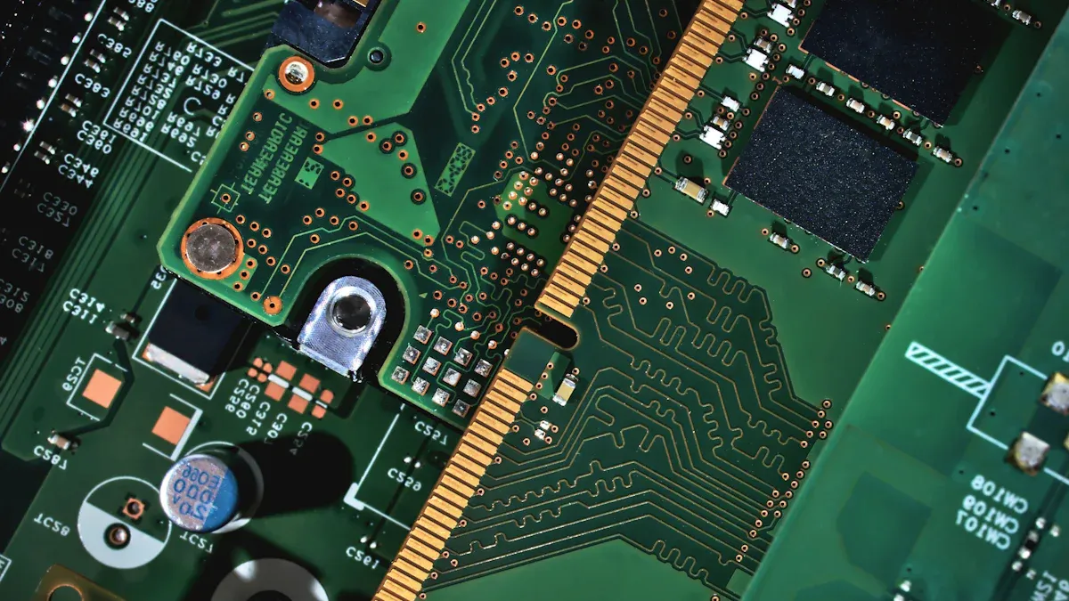
You find traces on every pcb. Traces are copper pathways that carry current and voltage between electronic components. Internal traces do not dissipate heat as well as external traces. Vias are plated holes that allow signals to move between layers. You use through-hole, blind, buried, and microvias depending on your pcb design.
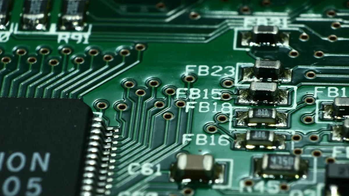
Pads are the surface areas where you solder electronic components. Annular rings surround vias and provide mechanical support and electrical connectivity. The silkscreen layer gives you markings and identifiers, making assembly and troubleshooting easier. Reference designators help you locate each component on the circuit board. Fiducial marks are alignment points for automated assembly machines. Test points allow you to measure voltage and current during testing. The bare board is the pcb before you add any components.
Tip: Do not assume the largest circuit board is always the main board. You need to check the function and connections before making decisions in troubleshooting.
Arrays are groups of circuit boards manufactured together and separated after assembly. Copper pour fills large areas with copper to improve current flow and heat dissipation. Layers refer to the number of conductive and insulating sheets in your pcb design. DRC (Design Rule Check) is a software process that verifies your pcb design meets manufacturing standards.
You often see FR4 as the base material for circuit boards. FR4 is a flame-retardant fiberglass that provides strength and insulation. You select FR4 for most pcb manufacturing projects because it balances cost and performance.
Circuit Components
You need to know the types of electronic components used in circuit board assembly. Microcontrollers and ICs (integrated circuits) are the brains of digital and analog systems. These components control current and voltage in your circuit. Capacitors and resistors manage voltage and current flow. Incorrect polarity or excessive heat can damage these components.
Component Type | Importance and Vulnerabilities |
|---|---|
Microcontrollers and ICs | Heart of electronic systems, sensitive to ESD and thermal stress, can lead to system failure. |
Capacitors and Resistors | Manage voltage and current, vulnerable to incorrect polarity and excessive heat. |
Connectors and Switches | Critical for user interaction, prone to mechanical stress and wear, can lead to connection issues. |
Fine-Pitch Components | Prone to soldering defects, can lead to poor electrical connections. |
High-Power Components | Susceptible to overheating, require proper heat dissipation. |
Electrolytic Capacitors | Limited lifespan, sensitive to temperature and voltage stress, can leak or fail. |
Connectors and switches allow you to interact with your circuit board. These components can wear out or break under mechanical stress. Fine-pitch components require precise soldering to avoid poor electrical connections. High-power components need proper heat dissipation to prevent overheating. Electrolytic capacitors have limited lifespans and can leak if exposed to high voltage or temperature.
You use active components like transistors and diodes to control current and voltage in analog and digital circuits. Passive components such as resistors and capacitors store or release energy. LEDs (light-emitting diodes) provide visual indicators or lighting in your electronics projects.
You create a bill of materials (BOM) to list every component needed for your pcb assembly service. The BOM helps you organize your circuit board assembly and ensures you order the correct electronic components.
Assembly Processes
You must understand the main assembly processes in pcba electrics. Surface Mount Technology (SMT) uses automated machines to place components on the pcb. You apply solder paste, position components, and use reflow soldering to create strong connections. Through-Hole Technology (THT) involves inserting components through holes in the circuit board and soldering them for robust connections. THT is ideal for high-current applications.
SMT uses automated pick-and-place machines for precise component placement.
Reflow ovens control temperature profiles to prevent component damage during reflow soldering.
Wave soldering machines ensure uniform solder coverage on through-hole leads.
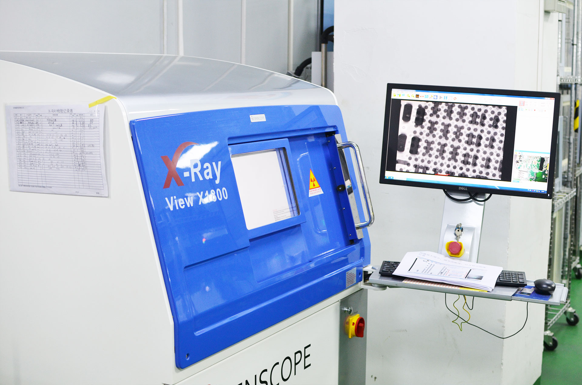
LTPCBA uses advanced assembly processes to meet industry standards. X-ray alignment systems achieve layer-to-layer registration within 0.05mm, which is essential for high-density pcb design. Automated printers adjust for stencil wear and paste viscosity, ensuring consistency. Automated pick-and-place machines position components with micron-level accuracy and can place up to 46,000 components per hour. Rigorous quality checks include AOI, X-Ray Inspection, ICT, Functional Testing, and Environmental Testing. LTPCBA holds certifications such as ISO 9001, IPC-A-610 Class 3, and UL compliance.
Note: PCBA introduces complexity compared to bare circuit boards. You need quality control measures to ensure your circuit board assembly functions reliably.
Arrays allow you to manufacture multiple circuit boards at once, improving efficiency. You must address issues like incorrect component orientation and poor solder joints to prevent malfunctions. High precision in component placement and soldering maintains signal integrity in digital and analog circuits.
Testing & Quality
Testing and quality assurance are crucial in pcba electrics. You use In-Circuit Testing (ICT), Flying Probe Testing, Functional Testing, Automated Optical Inspection (AOI), and X-Ray Inspection to verify your circuit board assembly. Aging Testing, Solderability Testing, PCB Contamination Testing, Cross-Section Analysis, Time-Domain Reflectometry (TDR) Testing, Peel Test, Solder Float Test, and Wave Soldering Test help you detect defects and ensure reliability.
PCBA testing ensures that your circuit boards and electronic components work according to design specifications. You catch issues early, allowing you to fix problems and maintain high product quality. Visual inspection, electrical testing, functional testing, environmental testing, reliability testing, and documentation review are standard steps in the process.
LTPCBA achieves a 99.5% first-pass yield, which is higher than typical industry benchmarks. The defect rate is less than 100 DPMO, showing LTPCBA’s commitment to quality. You benefit from rapid turnaround and 24/7 support when you choose LTPCBA for your pcb assembly service.
Tip: Do not overlook practical constraints in pcb design. A beautiful design does not guarantee functionality. You need to balance signal integrity, thermal management, and material choices.
You see trends in pcba electrics such as process automation, high-power circuit boards, miniature circuit boards, flexible circuit boards, and sustainable designs. You must stay updated with these trends to improve your electronics projects.
You may struggle with technical terms in pcb design. You overcome these challenges by learning best practices and focusing on practical applications. Strategic planning and precise layout techniques help you address signal integrity and thermal management issues. Material choices affect the performance of your circuit board assembly.
Printed Circuit Board Assembly Acronyms
Understanding acronyms and jargon in the world of printed circuit board assembly helps you communicate with engineers, suppliers, and manufacturers. These terms save time and prevent misunderstandings during your projects. You will see these acronyms in technical documents, emails, and meetings every day.
Industry Acronyms
You encounter many acronyms in the pcb assembly industry. Each one stands for a specific process, tool, or concept. Knowing these acronyms helps you follow instructions and understand technical discussions.
Meaning | |
|---|---|
SMT | Surface Mount Technology |
BGA | Ball Grid Array |
AOI | Automated Optical Inspection |
DRC | Design Rule Check |
BOM | Bill of Material |
PCB | Printed Circuit Board |
PCBA | Printed Circuit Board Assembly |
ICT | In-Circuit Test |
THT | Through-Hole Technology |
NRE | Non-recurring Engineering |
MOQ | Minimum Order Quantity |
UL | Underwriters Laboratories |
ISO | International Organization for Standardization |
IATF | International Automotive Task Force |
EMS | Electronics Manufacturing Service |
AQL | Acceptable Quality Limit |
PFMEA | Process Failure Mode Effects Analysis |
You use acronyms like SMT and BGA to describe how you mount components on a board. SMT refers to placing components directly onto the surface, while BGA describes a type of package with solder balls underneath. AOI stands for Automated Optical Inspection, which checks for defects after assembly. DRC means Design Rule Check, a software process that ensures your design meets manufacturing rules.
Using these acronyms makes your communication clear and efficient. You avoid long explanations and reduce the risk of errors in your pcb assembly projects.
You see how technology shapes these terms. In the 1960s, through-hole technology was the main method. The 1970s brought surface-mount technology, which made assembly faster and more reliable. By the 1980s, SMT became standard, allowing for smaller and more complex boards.
Common Jargon
You also hear many jargon terms in the printed circuit board assembly field. These words describe steps, materials, and issues you face during production.
Definition and Application | |
|---|---|
Punching | Creating holes for components, often in single or double-layer boards. |
Melting solder to attach components, then letting it solidify. | |
Reference Designator | Letters and numbers that identify each component on the board, such as "R1" for a resistor. |
Resist | A coating that protects certain areas during etching or soldering. |
Short | An unwanted connection that causes high current and possible damage. |
Silkscreen | Printed labels and markings on the board for identification. |
Solder | Metal alloy used to join components to the board. |
Solder Mask | A protective layer that covers the board except for solder points and fiducial marks. |
Stuff | The process of mounting and soldering components onto the board. |
Sub-Panel | A group of boards arranged together for easier handling during assembly. |
You use "reflow" when you heat the board to melt solder and secure components. "Stuff" means placing and soldering parts onto the board. If you find a "short," you know there is an unwanted connection that needs fixing. The "silkscreen" helps you identify parts quickly during assembly or repair.
Tip: When you read a board layout, always check the reference designators. They guide you to the correct component and prevent mistakes.
LTPCBA Standards
You want your printed circuit board assembly to meet the highest quality standards. LTPCBA follows strict international certifications to ensure every board meets customer expectations.
Description | |
|---|---|
ISO | Focuses on quality management and continuous improvement. |
IATF | Sets standards for automotive pcb assembly, ensuring safety and reliability. |
UL | Verifies the strength of the factory’s systems and requires ongoing quality management. |
You benefit from these certifications in several ways:
Improved communication between teams and clients.
Increased efficiency and lower costs.
Standardized work processes for consistent results.
Better quality control and fewer defects.
Higher customer satisfaction and repeat business.
You see these standards in action at LTPCBA. For example, when you order a batch of boards, you receive products that pass strict quality checks. The company uses AOI and X-ray inspection to catch defects early. By following ISO and IATF guidelines, LTPCBA ensures your boards work reliably in demanding environments, such as automotive or industrial applications.
Ongoing training keeps LTPCBA’s team up to date with the latest pcb assembly techniques and standards. You can trust that your projects benefit from the newest knowledge and best practices in the industry.
Note: Staying familiar with these acronyms and standards helps you succeed in electronics. You can communicate clearly, avoid mistakes, and deliver high-quality results every time.
You build stronger electronics projects when you understand PCBA electrics and printed circuit board terms. A glossary helps you succeed long-term:
Term | Definition |
|---|---|
PCB | Printed Circuit Board, a board used to connect electronic components. |
PCBA | Printed Circuit Board Assembly, the process of soldering components onto a PCB. |
Explore LTPCBA’s knowledge blog for tips and insights.
Bookmark this guide for quick reference and visit LTPCBA’s website for more resources.
FAQ
What is the difference between PCB and PCBA?
A PCB is a bare board with copper traces. A PCBA has all components mounted and soldered, ready for use in electronic devices.
Tip: Always check if you need a bare board or a fully assembled board for your project.
Why should you choose LTPCBA for your assembly needs?
You get high-quality assembly, fast turnaround, and strict quality control. LTPCBA follows international standards and offers 24-hour technical support.
How do you identify a test point on a printed circuit board?
Look for small, labeled pads or pins marked as "TP" on the silkscreen. These spots help you measure voltage or signals during testing.
See Also
Understanding PCBA And Its Key Components Explained
Defining PCBA: Its Meaning In The Electronics Field
Comprehensive Overview Of PCBA Manufacturing For All Levels
Sourcing Electronic Components For Effective PCBA Production