The basic requirements for components and PCBS in SMT assembly wave soldering process

You need to follow the basic requirements for components and PCBs in the SMT assembly wave soldering process. Good soldering depends on meeting these basic requirements. Clean parts, careful PCB design, and strict process steps help prevent problems and create strong solder joints. The table below highlights why these basic requirements are essential for quality assembly:
Statistic | Description | Impact on Soldering Process |
|---|---|---|
70% | Soldering problems from bad solder paste printing | Demonstrates the need for careful process steps |
5-8% | Increase in good products from improved process order | Confirms the importance of following basic requirements |
15% | Repairs needed due to tombstone effects | Emphasizes the significance of correct part placement |
You can rely on LTPCBA to adhere to these basic requirements in every assembly process.
Key Takeaways
Pick parts that have clean, heat-resistant leads. Make sure the materials are strong. This helps solder joints stay reliable. It also stops damage during wave soldering.
Use good PCB materials. Design your board with care. Give enough space between parts. Make pads and layout right. This helps stop soldering problems. It also makes assembly better.
Follow all wave soldering steps closely. Put on flux the right way. Preheat the board with care. Set the solder wave just right. This makes solder joints strong and last long.
Basic Requirements for Components
Picking the right parts is very important in wave soldering. You must follow strict rules to make sure each part works with your PCB and the process. LTPCBA uses a careful way to pick parts. They work with trusted suppliers and check quality often. This helps stop problems and makes sure your PCB assembly is reliable.
Component Types
You need to pick parts that work with wave soldering. Both surface mount and through-hole parts must meet the basic requirements. LTPCBA works with original makers and agents for important parts like ICs, resistors, and capacitors. These partnerships last 5 to 10 years. This gives you steady supply and good quality. LTPCBA checks suppliers every year to make sure they meet high standards. This way, you get parts that are reliable and easy to track for your PCB assembly.
Tip: Always make sure your parts can handle wave soldering. Do not use parts that cannot take the heat or stress from the wave.
Thermal Resistance
Thermal resistance is very important when picking parts. During wave soldering, parts get very hot. If a part cannot take the heat, it may break or cause problems in your PCB. Studies show solder joints do not last as long if heat changes a lot. More heat can make solder joints up to 40% weaker. Parts with big differences in thermal expansion, like the 192CABGA, can fail faster. You should always pick parts with high thermal resistance to keep your assembly strong.
Mechanical Strength
Mechanical strength helps parts survive wave soldering and later use. You need parts that can take the force of the solder wave and handling. Weak parts may crack or break, causing your PCB to fail. LTPCBA tests parts for mechanical strength as part of their checks. This keeps your assembly strong and reliable.
Electrical Compatibility
Electrical compatibility is another basic rule. You must match the ratings of your parts with your PCB design and the process. If you use parts with the wrong voltage or current, your PCB may get damaged or fail. LTPCBA checks every part for electrical compatibility before assembly. This step helps you avoid mistakes and keeps your PCB safe.
Lead and Body Materials
The materials for leads and part bodies matter a lot for soldering. You need clean, oxidation-free leads for good solder joints. The IPC J-STD-001 standard says clean leads stop contamination and help solder stick well. You should also make sure the lead length is between 0.8 mm and 3 mm for best results. LTPCBA uses AOI and X-ray checks to make sure leads are clean and shaped right. Solderability tests need at least 95% solder on leads, showing how important clean leads are for your assembly.
Note: Always keep your parts in a dry, clean place. This stops oxidation and keeps your leads ready for soldering.
Requirement | Why It Matters for Wave Soldering | LTPCBA Practice |
|---|---|---|
Clean, oxidation-free leads | Makes sure solder sticks and joints form well | AOI and X-ray check every batch |
Proper lead length | Stops soldering problems and makes strong joints | Visual checks and solder tests |
High thermal resistance | Lowers risk of breaking during soldering | Supplier checks and quality tests |
Mechanical strength | Stops damage during assembly and use | Strong part testing |
Electrical compatibility | Stops electrical problems in PCB assembly | Checks before assembly |
You must follow these basic rules for parts to get good PCB assembly. LTPCBA’s experience and strict standards help you get the best results in every wave soldering process.
PCB Requirements

Printed circuit boards are very important in wave soldering. You need to use good materials and follow strict rules. This helps make strong solder joints and keeps the assembly working well. LTPCBA uses new technology and follows world standards like ISO and UL. This makes sure you get good results. Here are the main things you need for PCBs in wave soldering.
Material and Heat Resistance
Pick PCB materials that can take high heat from wave soldering. If you use weak materials, the board can bend or break apart. Modern boards use special materials like high-Tg FR-4, polyimide, PTFE, and ceramic. These materials stay strong and do not get damaged by heat.
Key Properties & Benefits | |
|---|---|
Insulated Metal Substrate | Metal base (aluminum) for great heat control; special layer moves heat away; stops hot spots |
High Temperature FR-4 | Can take more heat (up to 180°C+), does not break apart, keeps its shape |
Polyimide | Handles heat up to 260°C, keeps its shape, resists chemicals and radiation |
Ceramic-Based Substrates | Can take over 500°C, moves heat well, does not lose power; good for tough places |
You should also use boards with special solder masks and pastes for high heat. These help the board keep its shape and strength during soldering. LTPCBA uses these materials and checks quality to make sure your boards stay strong.
Solder Mask Quality
The solder mask covers the PCB during wave soldering. A good solder mask stops solder from going where it should not. You need a mask that can take high heat and does not get hurt by chemicals. LTPCBA uses silicone and high-heat solder masks for better safety.
Tip: Always look for even coverage and no holes in the solder mask. This helps stop problems and keeps soldering easy.
A good solder mask also makes your boards look better. It helps you find problems when you check the boards. LTPCBA checks every board to make sure the solder mask is good.
Copper Adhesion
Copper adhesion is needed for strong solder joints. If copper does not stick well, soldering will not work and joints will be weak. You must make sure the copper layer sticks tight to the board. Factories use pull force tests to see how strong the bond is. Plasma treatment can make the bond up to 300% stronger. The board must be very clean. Even a little dirt can make the bond weak. LTPCBA uses special tests to check if the surface is ready and copper will stick well.
Warpage Control
Warpage can cause big problems in wave soldering. If the PCB bends or twists, solder may not reach all pads. This can make weak joints or open circuits. You need to use good materials and careful steps to stop warpage. LTPCBA uses a special test called IPC-TM-650 2.4.22.1. This test has helped lower defects by 68% in some cases. Always check if the board is flat before soldering.
Surface Cleanliness
A clean surface is very important for good soldering. Dirt or oil can stop solder from sticking to the pads. You need to use different ways to check if the surface is clean. These include looking closely, ROSE testing, ion chromatography, and contact angle tests. ROSE testing is fast and cheap, but only shows average dirt. Contact angle tests show how well the surface will take solder or coatings.
Description / Purpose | |
|---|---|
Visual Inspection | Look at the board with a magnifier to find big dirt or rust. |
ROSE Testing | Checks for ionic dirt by testing how a solvent works on the board. |
Ion Chromatography | Measures how much ionic dirt is in the cleaning liquid. |
Contact Angle Measurement | Checks the angle of a water drop to see if the surface is clean. |
Surface Insulation Resistance | Tests how well the board keeps electricity from leaking due to dirt. |
LTPCBA uses these tests to make sure every board is clean and meets high standards. Clean boards help you get strong solder joints and reliable assemblies.
Note: Always keep your PCBs in a clean, dry place before soldering. This stops dirt and helps you get the best results.
You must follow these rules for PCB materials, solder mask, copper adhesion, warpage, and cleanliness. LTPCBA’s focus on quality and world standards helps you get strong wave soldering and long-lasting boards.
PCB Assembly Design
Component Layout
You should plan where to put each component. Start by placing parts near the edges first. This makes building the board easier. Put similar parts together in groups. Try to point them in the same direction. This helps you make fewer mistakes when placing parts. It also helps during wave soldering. Keep high-frequency parts close to each other. This makes signals work better. LTPCBA uses special cameras to check for mistakes early. This helps you get more good boards from each batch.
Pad Design
Pad design is important for strong solder joints. Solder mask-defined pads stop solder from joining where it should not. This is helpful for small, close-together parts. Pads without a solder mask let solder stick better for normal parts. Always follow the IPC-7351 rules and check the part’s datasheet. LTPCBA looks at your pad design before starting. This makes sure your board meets all the rules for wave soldering.
Clearances and Spacing
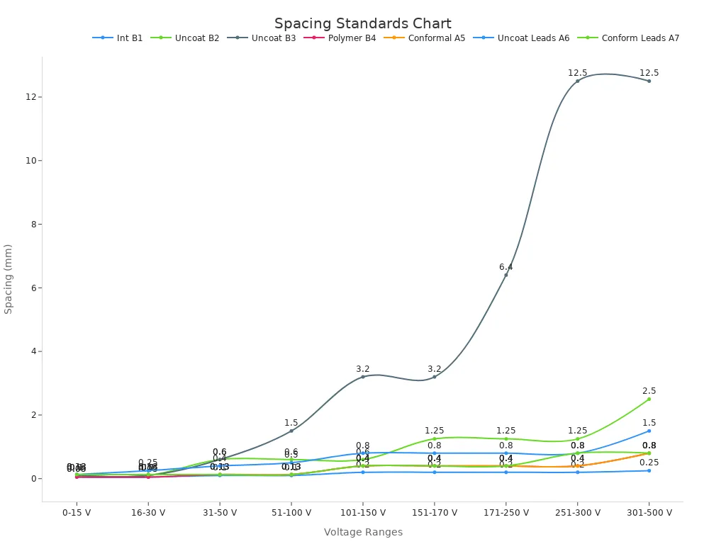
Good spacing stops short circuits and soldering problems. The IPC-2221B rule tells you how much space you need. The space depends on voltage and the type of metal line. For example, you need at least 0.1 mm between bare metal lines at low voltage. Use these numbers to keep your board safe and working well.

Orientation
Make sure all parts face the same way. This step helps you place parts with fewer mistakes. It also makes wave soldering go smoother. When ICs and other parts are lined up, it is easier to check them.
Shadowing and Bridging
Shadowing happens when big parts block the solder wave. This can make weak joints. Put tall parts after smaller ones in the wave’s path. Leave enough space between parts to stop solder from joining them by mistake. LTPCBA checks your board design before building it. This helps find these problems early. You get better boards when you follow these tips.
Tip: Always ask your assembly partner to check your design before building. LTPCBA uses special methods and checks to make sure your board meets all the rules for wave soldering.
Wave Soldering Process Essentials

Flux Application
You must put solder flux on every pcb before soldering. Solder flux cleans off oxidation and helps solder flow well. This step is very important in the process. You need to pick the right solder flux for your job. Rosin-based, acid-based, and no-clean solder fluxes work best for different needs. Always clean the pcb surface before adding solder flux. This helps solder stick and make strong joints. Use the right amount of solder flux to stop problems like bridging or weak joints. LTPCBA follows IPC J-STD-001G rules for using solder flux. This makes sure the soldering is high quality.
Tip: Using solder flux the right way helps make strong joints and lowers defects in your pcb assembly.
Preheating
Preheating gets your pcb ready for wave soldering. You need to warm it up slowly, about 1 to 3°C each second. This step makes the solder flux work and stops thermal shock. Preheating also helps solder flow better and stops cold joints. The best preheating temperature is between 100°C and 125°C for most jobs. The whole pcb must heat up evenly. LTPCBA uses special controls to keep preheating steady and safe.
Solder Wave Parameters
You must control the solder wave’s height, temperature, and speed. The solder wave should touch all joints and pads on the pcb. The best soldering temperature is between 230°C and 250°C. This range gives good solder fill and strong bonds. If the temperature goes over 250°C, more oxidation happens and can hurt the joints. LTPCBA uses data to set solder wave settings. This helps make better assemblies and more good boards.
Parameter | Recommended Setting | Effect on Soldering Process |
|---|---|---|
Solder Wave Temp | 230°C–250°C | Strong solder joints, less oxidation |
Solder Wave Height | Covers all pads | Complete soldering of all joints |
Solder Wave Speed | Controlled | Prevents bridging and weak joints |
Conveyor Speed
You need to set the conveyor speed to fit your pcb’s heat needs. If the conveyor is too fast, joints may not get hot enough. If it is too slow, you can get too much heat and oxidation. New soldering lines with more heat zones can go faster and still keep the right heat. LTPCBA changes conveyor speed for each job. This makes sure every joint is good quality.
Inspection and Quality Control
Inspection is very important in wave soldering. Automated Optical Inspection (AOI) checks each pcb for problems like bad joints, missing parts, or solder bridges. AOI finds problems much faster than people can. LTPCBA uses AOI and other machines to make sure each pcb is high quality. AOI also gives data to help improve the process and stop future problems. This focus on quality control helps you get strong and reliable assemblies.
Note: AOI can find up to 90% of problems, making your pcb assembly better and lowering repair costs.
You must do some important things for a strong pcb assembly. Always use clean parts and materials that can take heat. Plan your pcb design with care. Look for solder bridges and missing joints. Make sure the flux works well. Use machines to check and test your pcb. This helps you find problems you cannot see. LTPCBA checks every pcb to make sure it is good and customers are happy.
Remember: Using a checklist helps you follow all pcb rules.
FAQ
What are the basic requirements for components in the wave soldering process?
You need to use parts with clean leads. The leads should not have any rust. The lead length must be right for the job. Parts also need to handle high heat. These things help make strong solder joints. They also help your pcb assembly work well.
How does pcb design affect solder joint quality during wave soldering?
A good pcb design puts parts in the right spots. It uses pads that fit the parts well. There is enough space between each part. These steps help stop weak solder joints. They also make your assembly better.
Why is solder flux important in the wave soldering process?
Solder flux cleans the board and the parts. It helps the solder move and stick where it should. This makes the joints strong. It also helps stop mistakes in your soldering.
See Also
Essential Instructions For Wave Soldering In SMT Assembly
Key Specifications For Wave Soldering During DIP Assembly
Fundamental Criteria For PCB Boards Used In SMT Manufacturing
Critical Process Standards For Reflow Soldering In SMT
Common Causes Of Component Detachment During SMT Wave Soldering
