This guide will show you how to assemble Rogers PCBs for high-frequency applications
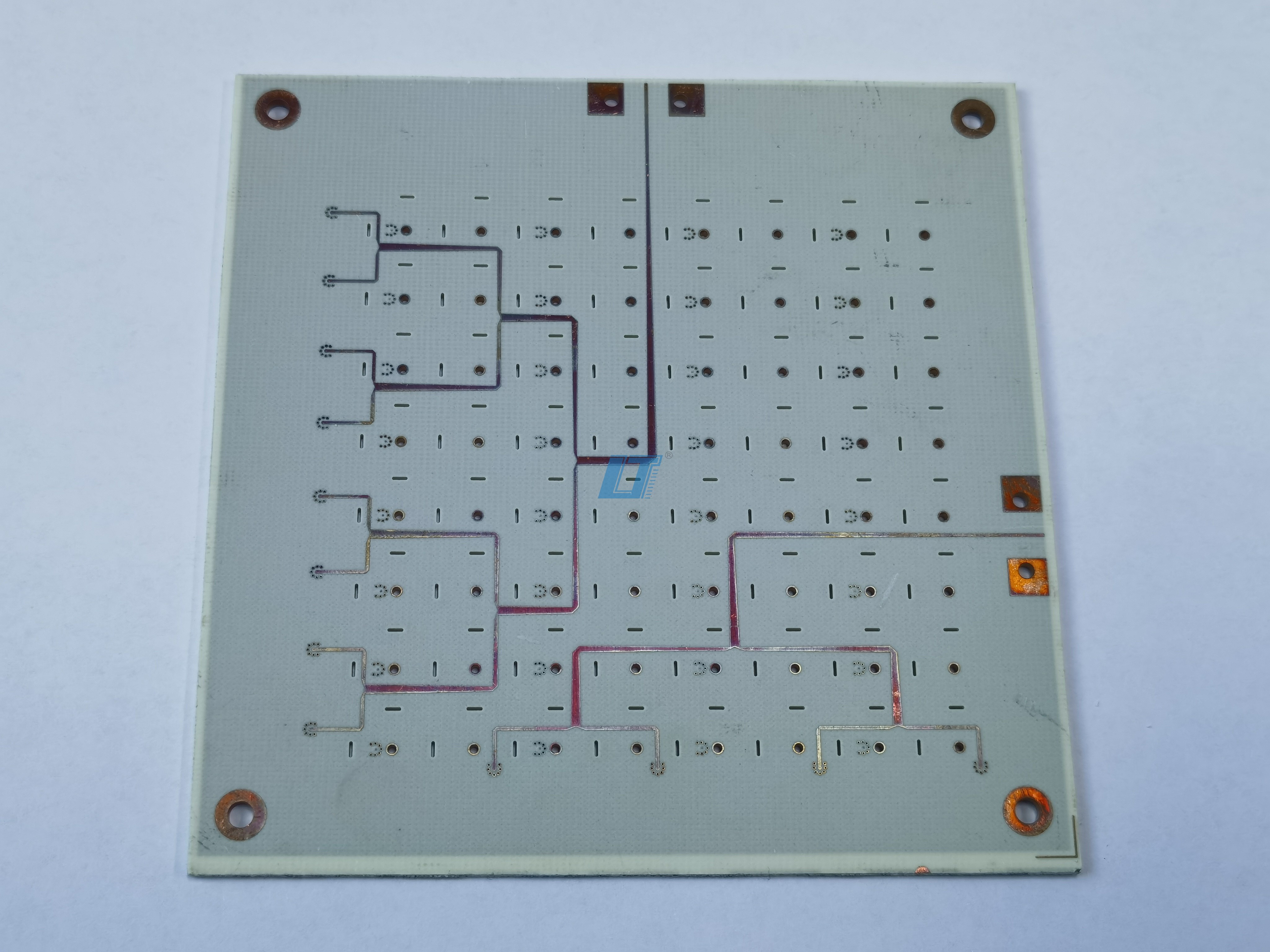
You face unique challenges when working with assembly rogers pcb for high-frequency applications. High-frequency printed circuit board designs demand careful impedance control and strategic layout. Common issues include managing complex wiring, ensuring power integrity, and maintaining isolation between analog and digital sections.
High-frequency PCBs appear in telecom, automotive radar, aerospace, and medical devices.
By focusing on process and quality, you can achieve optimal results with support from LTPCBA.
Key Takeaways
Choose Rogers materials for low dielectric loss and thermal stability. This ensures reliable signal transmission in high-frequency applications.
Optimize wire layout and impedance control. Use best practices like avoiding sharp angles and minimizing vias to maintain signal integrity.
Collaborate with LTPCBA for quality assurance. Their advanced inspection processes help catch defects early and ensure your PCB meets high standards.
Assembly Rogers PCB Steps
Material Selection
You start the assembly rogers pcb process by choosing the right materials. Rogers materials stand out for high-frequency electronic equipment because they offer properties that standard substrates cannot match. The table below shows why you should select rogers for your high-frequency designs:
Property | Description |
|---|---|
Low Dielectric Constant | Minimizes signal loss and ensures efficient signal transmission at high frequencies. |
Low Loss Tangent | Preserves signal strength and quality over long distances or at high speeds. |
Thermal Stability | Maintains performance consistency in fluctuating temperatures, reducing signal distortion. |
Mechanical Stability | Provides robustness and durability to the PCB, essential for high-frequency applications. |
Signal Integrity | Critical for minimizing data loss and ensuring reliable communication in high-speed applications. |
Flexibility | Allows for tailored designs to meet specific application requirements, such as impedance control. |
When you compare rogers to standard materials like FR4, you see a clear advantage for high-frequency applications. For example, Rogers 5880 has a dielectric constant of 2.20, which means low signal attenuation and better performance. FR4, with a higher dielectric constant, cannot deliver the same results. Rogers RO4350B, with a dielectric constant of 3.48, also maintains excellent impedance control for RF circuits.
You should also consider the surface finish. ENIG and immersion gold finishes enhance signal integrity and prevent corrosion, which is important for long-term reliability. LTPCBA offers a variety of finishes and helps you select the best option for your assembly rogers pcb project.
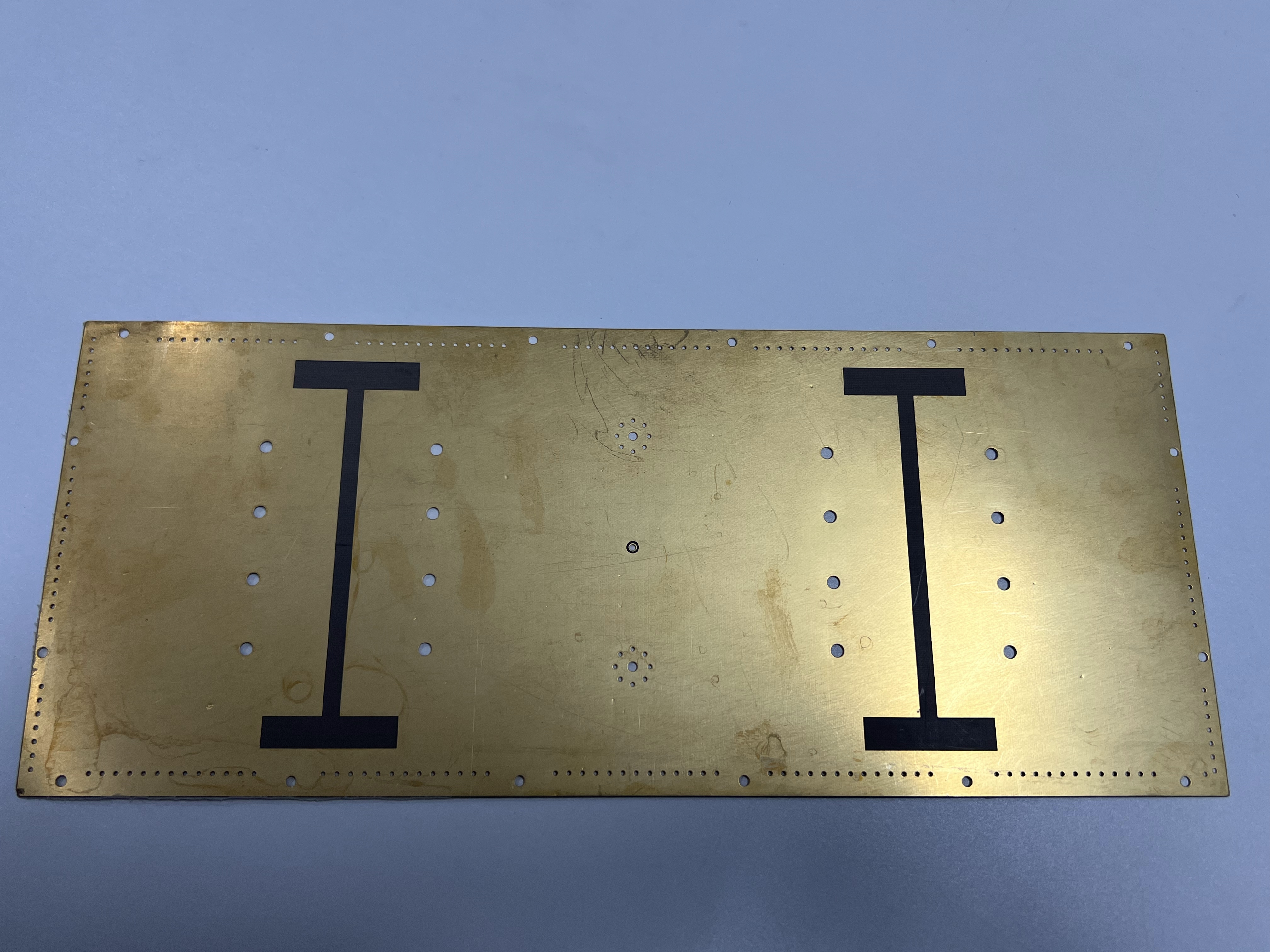
Laminate Construction
Next, you focus on laminate construction. The thickness of the laminate impacts signal integrity and thermal stability. Thicker laminates in rogers pcb improve heat management and maintain performance in high-frequency environments. For example, Rogers 4003C comes in thicknesses from 0.002” to 0.062”, making it suitable for many designs. RO4350B, often used in high-frequency applications, offers similar flexibility in thickness.
You should choose the laminate thickness based on your design needs. Thicker laminates help with thermal stability, while thinner laminates allow for compact layouts. LTPCBA uses advanced lamination techniques, including multilayer stacking, to build complex assembly rogers pcb structures. Their high-precision drilling ensures accurate alignment between layers, which is critical for signal integrity.
You also need to select a solder mask that prevents signal degradation. A low-loss solder mask with controlled thickness keeps impedance stable and supports high-frequency performance.
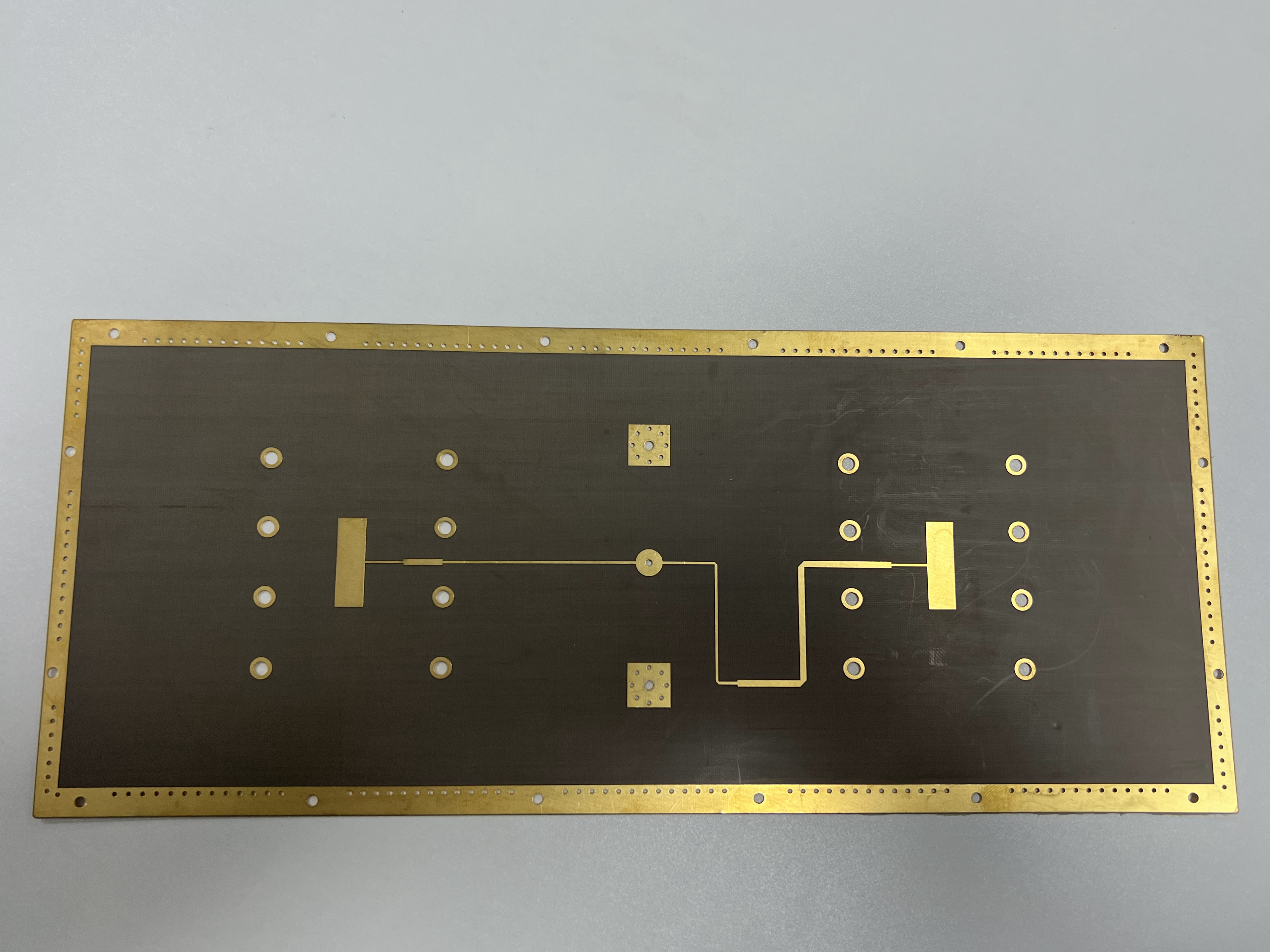
Wire Layout & Impedance
Wire layout and impedance control are key steps in assembly rogers pcb. You must optimize trace width and spacing to maintain signal integrity. Use the following best practices:
Optimize trace width and spacing for the required impedance.
Avoid sharp angles in traces. Use smooth curves or 45-degree bends to prevent signal reflections.
Minimize the use of vias. Each via can cause impedance changes and signal reflections, which degrade performance.
Match the length of differential pairs to avoid timing issues.
Use dedicated ground and power planes to reduce crosstalk and provide a low-resistance return path.
Increase the distance between high-speed signal traces to minimize crosstalk.
Surround critical traces with ground or power planes for shielding.
Tip: The 3W rule states that the center-to-center spacing between traces should be at least three times the trace width. This reduces crosstalk, especially for high-speed signal lines.
Impedance control is essential for high-frequency signals. Proper impedance matching ensures smooth signal transmission and reduces the risk of reflections and interference. Without it, you may see signal distortion and data loss.
LTPCBA specializes in controlled impedance design and microstrip or stripline layouts. Their expertise in assembly rogers pcb includes advanced techniques like thermal management, multilayer lamination, and automated optical inspection. These methods help you achieve low loss and high stability, which are crucial for high-frequency performance.
You benefit from LTPCBA’s experience with complex rogers pcb assemblies. Their team supports you from material selection to final inspection, ensuring your pcb assembly meets the demands of high-frequency electronic equipment.
High-Frequency Rogers PCB Considerations
Why Choose Rogers
You need materials that support reliable signal transmission in high-frequency applications. Rogers materials offer unique electrical properties that make them ideal for RF and microwave circuits. The table below compares Rogers materials to standard FR-4:
Property | Rogers Materials | FR-4 |
|---|---|---|
Dielectric Loss (Df) | 0.0009 to 0.0037 | 0.02 |
Dielectric Constant (Dk) | 2.2 to 10.2 | ~4.5 |
Thermal Conductivity | 0.6-0.8 W/mK | 0.1-0.5 W/mK |
Moisture Absorption | As low as 0.1% | Up to 0.5% |
CTE | ~18 ppm/°C | Not specified |
Rogers materials provide low loss and stable dielectric properties across a wide frequency range. You get consistent performance even in demanding environments. These features help you achieve high reliability and performance in your rogers pcb designs for high-frequency electronic equipment.
Quality Assurance & PCB Assembly at LTPCBA
You want your rogers pcb to meet strict quality standards. LTPCBA uses advanced quality assurance processes for every assembly. The table below shows the steps LTPCBA follows:
Quality Assurance Process | Description |
|---|---|
DFM Reviews | Identifies manufacturing challenges early |
Material Selection and Sourcing | Ensures high-quality rogers and components |
Manufacturing Process Control | Uses automated systems for consistency |
Final Inspection and Testing | Verifies functionality before shipping |
Automated Optical Inspection | Scans for surface defects |
X-ray Inspection | Detects hidden defects in multilayer PCBs |
In-Circuit and Functional Testing | Checks electrical performance and simulates real-world conditions |
Environmental Stress Testing | Tests durability under extreme conditions |
LTPCBA also uses automated inspection technologies. These include AOI, SMT first article inspection machines, and SMT X-ray inspection systems. These tools help you catch defects early and ensure your rogers pcb meets the highest standards.
Testing & Support
You need to test your rogers pcb to guarantee reliability and performance. Best practices for testing high-frequency assemblies include:
Verify functionality of each component and circuit.
Detect manufacturing defects such as soldering issues.
Improve yield and reduce rework costs by catching problems early.
Ensure reliability and performance under extreme conditions.
Meet customer and certification requirements.
You can use several test methods:
AOI scans for visual defects.
AXI checks hidden solder joints.
FCT simulates real-life performance.
ICT tests for shorts and opens.
Flying probe tests suit prototypes.
For high-frequency applications, you may also use high-performance oscilloscopes, vector network analyzers, and time-domain reflectometry. These tools help you measure signal integrity and confirm your rogers pcb performs as expected. LTPCBA provides technical support and guidance throughout the testing process, helping you achieve the best results for your high-frequency designs.
You achieve reliable high-frequency pcb assembly by following these steps:
Select Rogers materials for low loss and thermal stability.
Optimize layer stack-up and use simulation tools.
Collaborate with LTPCBA for quality control and testing.
Benefit | Rogers Materials |
|---|---|
Dielectric Stability | Superior |
Thermal Stability | Superior |
FAQ
What makes Rogers PCBs better for high-frequency circuits?
Rogers PCBs use special materials. You get lower signal loss and better stability. Your high-frequency designs work more reliably than with standard FR-4 boards.
How do you control impedance in Rogers PCB assembly?
You adjust trace width and spacing. You use ground planes. LTPCBA helps you simulate and verify impedance for your high-frequency needs.
Can LTPCBA support prototype and production runs for Rogers PCBs?
Service Type | Support Available |
|---|---|
Prototype | ✅ Yes |
Production | ✅ Yes |
You can order both prototypes and larger batches. LTPCBA provides quick quotes and technical support for every stage.
See Also
Choosing The Best Turnkey PCBA Manufacturer For Your Project
Comprehensive Overview Of PCBA Manufacturing For All Levels
Essential PCBA Processing Standards For Medical Devices
Best Practices For Assembling Flex PCBs Effectively
Sourcing Electronic Components For Effective PCBA Production