7 Essential Tips for PCBA Medical Device Design and Assembly
You face demanding expectations when you design and assemble a pcba medical device. Safety and compliance shape every decision because medical devices must protect patients and deliver consistent results. Regulatory frameworks in the US and Europe, such as FDA, CE marking, ISO 13485, and IEC 60601, establish strict standards for pcb quality, risk management, and traceability.
FDA (United States) | CE Marking (Europe) | |
|---|---|---|
Approval Process | Rigorous pre-market approval, often requiring detailed clinical trial data | Focus on demonstrating compliance with EU regulations, generally less stringent for lower-risk devices |
Clinical Data | Extensive clinical data required, often from US trials | Less stringent, more flexible clinical evidence accepted |
Quality System | Enforces Quality System Regulation (QSR) with specific procedures and documentation | Requires compliance with ISO 13485 standards, similar focus but different procedures |
Post-Market Surveillance | Robust system with mandatory adverse event reporting and inspections | Required but mechanisms and frequency differ; MDR emphasizes more rigorous surveillance |
Enforcement | Legally binding with FDA enforcement authority including recalls | CE mark indicates conformity; enforcement by member states; manufacturers self-declare compliance |
Classification System | Class I, II, III based on risk | Risk-based classification with different criteria |
Documentation | Formal submissions like PMA or 510(k) | Technical file or design dossier reviewed by notified body or self-certification for low-risk devices |
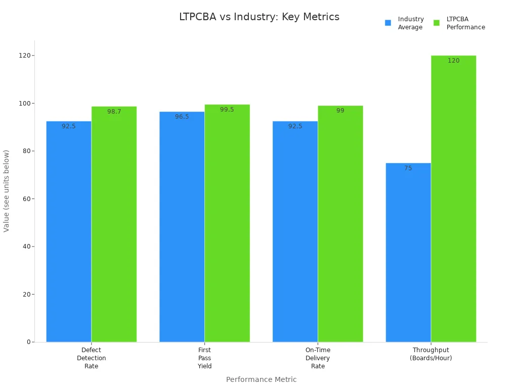
You need a partner who meets these standards and delivers reliable results. LTPCBA brings proven expertise to your medical device projects. Advanced testing, automated inspection, and a 99.5% first-pass yield help you achieve success with every pcb.
Trust industry best practices and LTPCBA’s experience to guide your design and assembly. You gain practical solutions for every stage of your medical device journey.
Key Takeaways
Prioritize safety by identifying risks early using methods like Failure Mode and Effects Analysis to prevent device failures and protect patients.
Use redundancy and fail-safe designs to ensure devices keep working safely even if parts fail, and include alarms to alert users of issues.
Select biocompatible materials and follow strict standards to avoid harmful reactions and meet global safety requirements.
Design test points strategically and implement traceability systems to improve fault detection, speed up repairs, and comply with regulations.
Choose medical-grade components and plan for obsolescence to maintain device reliability and avoid costly production delays.
Safety First in PCBA Medical Device
Risk and Hazard Analysis
You must prioritize safety when designing a pcba medical device. Risk and hazard analysis forms the foundation of every successful project. You start by identifying potential dangers that could affect patients or users. According to ISO 14971:2019, you need to consider risks such as biocompatibility, data security, electrical hazards, and usability. Common failure causes include manufacturing defects, packaging errors, and software glitches. You also face new risks from wireless communication and internet connectivity, which require expanded risk management to prevent cybersecurity threats.
Tip: Use a bottom-up approach like Failure Mode and Effects Analysis (FMEA) to analyze each component and assembly. This method helps you catch issues early and avoid mechanical damage, electrical failures, or device malfunctions.
Leading risk factors in pcba medical device projects include:
Biocompatibility and cleanliness
Sterilization and device-body interaction
Mechanical damage (scratching, cutting, piercing)
Electrical hazards
Manufacturing and component failures
You must address these risks to ensure the safety of life-critical medical devices.
Redundancy and Fail-Safes
Redundancy and fail-safe mechanisms are essential for life-critical medical devices. You can reduce the risk of malfunction by duplicating critical components or systems. If one part fails, a backup takes over immediately, maintaining safe operation. Fail-safe designs ensure that devices default to a safe state during faults, such as stopping medication delivery if a sensor fails.
Aspect | Explanation |
|---|---|
Redundancy Concept | Duplication of critical components ensures system functionality continues if one part fails. |
Benefits of Redundancy | Improved reliability, reduced downtime, enhanced safety by backup components taking over immediately. |
Design Principles | Independence of components, diversity to avoid common-cause failures, fault detection and isolation mechanisms. |
You should also include alarms and user feedback to alert users to out-of-range or failure conditions. These strategies, supported by FDA and IEC standards, help you maintain safety and reliability in pcba medical device projects.
Biocompatible Materials
Selecting biocompatible materials is crucial for medical device safety. You need to choose materials that do not cause adverse reactions when in contact with human tissue. Polyimide, PTFE, and FR4 are commonly used in medical PCBs. Polyimide offers flexibility and can be coated for enhanced biocompatibility. PTFE works well for sterilizable equipment, while FR4 is suitable for stationary parts with added barriers.
Material | Usage in Medical PCBA | Biocompatibility Profile | Safety Standards |
|---|---|---|---|
Polyimide | Flexible, body-conforming PCBs | Biocompatible with coatings | ISO 10993, FDA |
PTFE | Flexible, sterilizable equipment | Generally biocompatible | ISO 10993 |
FR4 | Stationary device parts | Needs biocompatibility barriers | Cost-effective, requires coatings |
LCP | Wearables, implantable sensors | Moisture resistant, moderate biocompatibility | ISO 10993, suitable for implantables |
You must comply with standards like ISO 13485, IEC 60601, and FDA 21 CFR Part 820 to ensure your pcba medical device meets global safety requirements. LTPCBA follows these standards, providing cleanroom manufacturing and rigorous quality control to protect patient safety.
Testability in Medical Devices
Strategic Test Point Placement
You improve reliability and speed up troubleshooting when you design strategic test points for medical devices. Placing test points in the right locations allows you to perform in-circuit testing and detect faults early. Bed-of-nails and flying probe methods both depend on accessible, well-distributed test points. You should avoid using component leads as test points and keep consistent spacing, usually 0.100 inches center-to-center. Distribute test points evenly across the PCB and keep them at least 0.125 inches from the edges.
Tip: Use square-shaped test points sized between 0.035 and 0.050 inches for better probe contact and identification.
For multi-layer boards, extend intermediate layer test points to the outer layers. This approach ensures you can reach every node and verify electrical performance. Cluster testing helps when you have limited test points, allowing you to check groups of components together. These strategies reduce fixture costs and improve defect detection in electronic medical devices.
Test Point Strategy | Benefit |
|---|---|
Even distribution | Prevents clustering and missed faults |
Proper spacing | Reduces risk of shorts and probe errors |
Avoiding obstructions | Ensures reliable contact during testing |
Optimal sizing and shape | Improves probe accuracy and throughput |
Traceability Systems
You need robust traceability systems to meet regulatory requirements and maintain quality in medical devices. Traceability links design elements, test cases, and deliverables, creating a verifiable audit trail. Regulatory bodies such as the FDA and EU MDR require systems like Unique Device Identification (UDI), which connect product identifiers to manufacturing history. ISO 9001 Clause 8.5.2 also supports identification and traceability as foundational standards.
Traceability provides enhanced quality assurance and faster issue resolution.
You gain supply chain integrity and regulatory compliance.
Root cause analysis becomes easier, and you build customer confidence.
Technologies such as RFID, barcode systems, IoT, blockchain, and AI analytics improve transparency and accountability.
Traceability systems allow you to identify faulty units by unique machine-readable IDs linked to batch and serial data. Shipping records tied to these IDs help you isolate affected products and manage recalls quickly. Version control logs every design change, supporting reliable audit trails and preventing the use of obsolete designs. Post-market surveillance relies on traceability to monitor device performance and collect user feedback. You minimize patient risk and ensure compliance with strict regulations.
Component Selection & Obsolescence
Medical-Grade Parts
You must select medical-grade parts that meet strict standards for safety and reliability. When you design a medical device, you need components that withstand harsh conditions such as temperature swings, moisture, and contamination. Class 3 electronics and circuit boards offer the durability required for medical applications. You should look for suppliers who provide parts with conformal coatings and stainless steel to resist corrosion and dust. These features help your device maintain performance in demanding environments.
Manufacturers like Salesmasters.com supply power supplies, batteries, sensors, and connectors designed for medical use. These components support patient monitoring, imaging, and diagnostics. You should verify that your suppliers comply with ISO certifications and FDA requirements. POE PCBA Solutions demonstrates the importance of clean, static-free assembly environments and multi-layer PCB capabilities. You benefit from lead-free assembly and functional testing, which ensure your medical device meets regulatory standards and delivers reliable operation.
Component Type | Medical-Grade Feature | Benefit for Medical Device |
|---|---|---|
Power Supply | Low noise, ISO certified | Stable, safe operation |
Sensor | High accuracy, IP69K rating | Reliable patient monitoring |
Connector | Stainless steel, sealed | Prevents contamination |
Obsolescence Planning
You face constant challenges from component obsolescence in medical device design. Proactive planning helps you avoid costly redesigns and production delays. You should monitor component lifecycles using forecasting tools and lifecycle databases. This approach lets you anticipate end-of-life issues before they disrupt your device production.
Tip: Use a decision tree to guide your strategy based on component status and available alternatives.
Effective strategies include:
Proactive obsolescence management—track parts early and prepare alternatives.
Last-Time Buy—purchase extra stock of critical components nearing end-of-life.
Redesign and requalification—update your device with new parts and validate compliance.
Supplier diversification—work with multiple suppliers to reduce risk.
Manufacturers use ERP systems and predictive analytics to manage supply chain risks. You should document every change and conduct verification testing to maintain compliance with ISO 13485. By planning ahead, you keep your medical device reliable and ready for market.
Manufacturability & Serviceability
Assembly Process Optimization
You can achieve high reliability in medical device PCBA by focusing on assembly process optimization. When you apply best practices during design and assembly, you reduce defects and improve product quality. Start by using Design for Manufacturability (DFM) and Design for Testing (DFT) principles. These help you optimize board layout and make testing easier.
Apply DFM and DFT to improve board performance and ease of assembly.
Use precise solder paste application to avoid excess or insufficient solder.
Optimize component placement to prevent misalignment and boost accuracy.
Control reflow soldering with multi-zone ovens for even heating and strong joints.
Implement rigorous inspection methods like Automated Optical Inspection (AOI), X-ray, and In-Circuit Testing (ICT) to catch defects early.
Continuously improve your process with data analysis, Lean manufacturing, and employee training.
Emphasize precision and process control to deliver consistent, high-quality results.
Tip: Partner with a certified manufacturer like LTPCBA. You gain access to advanced tools, quality assurance, and expertise in medical device standards.
By following these steps, you ensure your assembly process meets strict medical requirements and supports long-term device performance.
Maintenance Access
You must design your medical device PCBA for easy maintenance access. Good maintenance access allows you to replace or upgrade parts quickly, which keeps devices running and reduces downtime. Modular design makes this possible. When you use modular PCBs, you simplify repairs and upgrades. This approach also improves safety and reliability.
Modular PCBs allow for quick replacement and upgrades.
Accessible connectors and clear labeling make service tasks easier.
Sufficient spacing between components helps technicians reach parts without damaging the board.
High-quality assembly, strict adherence to standards like ISO 13485, and robust testing all support long-term reliability. When you focus on maintenance access during design and assembly, you help ensure your medical devices remain safe and dependable in real-world conditions.
Compliance in Medical PCB Assembly
Meeting regulatory and industry standards is essential for every medical pcb assembly project. You must follow strict protocols to ensure patient safety and product reliability. These standards guide your design, manufacturing, and testing processes, helping you deliver devices that meet high quality and safety standards.
Standards (ISO, IPC, UL)
You need to understand the main standards that apply to medical pcb assembly. These standards set the requirements for quality, safety, and performance.
ISO Standards:
ISO 13485 focuses on quality management systems for medical devices. It emphasizes regulatory compliance, risk management, and customer feedback.
ISO 14971 covers risk management for medical devices, helping you identify and control potential hazards.
IPC Standards:
IPC-A-600 and IPC-A-610 define acceptability criteria for PCB fabrication and assembly.
IPC-J-STD-001 sets requirements for soldered electrical assemblies.
IPC Class 3 is the highest reliability class, required for medical and aerospace electronics.
UL Standards:
UL 796 addresses safety for printed wiring boards.
UL 94 sets flammability standards for PCB materials.
You benefit from these standards by improving product quality, reducing defects, and gaining access to global markets. LTPCBA holds certifications in ISO, IATF, and UL, ensuring your projects meet international requirements.
Documentation & Validation
Proper documentation and validation are critical for regulatory approval. You must keep detailed records of every design decision, test result, and manufacturing process. This documentation supports audits and regulatory submissions.
Develop comprehensive testing and validation protocols, including functional, environmental, and biocompatibility tests.
Maintain a Design History File, Device Master Record, and Device History Record for traceability.
Use robust design controls, such as document management and change control, to ensure consistent quality.
Prepare regulatory submission packages with all required data and test results.
Implement post-market surveillance to monitor device performance and address any issues.
LTPCBA supports you with a strong quality management system and audit-ready documentation. You can trust their expertise to help you achieve compliance and deliver safe, effective medical devices.
Miniaturization in Designing a Medical Device PCB
Size vs. Reliability
You face constant pressure to reduce the size of your pcb when designing a medical device pcb. Miniaturization allows you to create compact, portable solutions for medical electronics design. Rigid-flex pcb technology helps you integrate multiple boards into one unit, eliminating connectors and reducing interconnect points. This approach saves space and removes potential failure points, which improves reliability. The flex portion of rigid-flex designs often occupies less than 20% of the space compared to traditional wired solutions.
Flexible pcbs give you more freedom in design. You can fit circuits into tight spaces and unusual shapes. These boards also handle thermal expansion better, which prevents connection failures. Rigorous environmental testing, such as HALT/HASS and vibration tests, confirms that flexible pcbs meet demanding standards for medical devices. You achieve high reliability, with some printed circuit board designs reaching mean time between failure ratings over 20 years.
Tip: When you focus on miniaturization, always balance size reduction with long-term reliability. Smaller devices must still meet IPC-6012DA Class 3 standards for medical safety.
EMI/EMC Considerations
Miniaturization in pcb design brings new challenges with electromagnetic interference (EMI) and electromagnetic compatibility (EMC). As you increase component density and pack traces closer together, signal degradation and crosstalk become more likely. You must address these risks early in the design process.
Design traces with controlled impedance, such as 50Ω single-ended or 100Ω differential pairs, to maintain signal integrity.
Use EMI shielding, including metal layers and filter capacitors, to reduce interference.
Separate sensitive traces from high-frequency components and add ground planes to shield critical signals.
Optimize your pcb layout to minimize loop areas and improve grounding.
Add ferrite beads, shielding, or filters to suppress EMI sources.
Conduct pre-compliance testing early to catch issues before final production.
Use simulation tools like Altium Designer or Ansys HFSS to predict EMI risks and optimize your pcb design.
High-density interconnect (HDI) technology helps you route finer traces and use multi-layer boards, which reduces board size and improves performance. Microvia technology saves space and lowers via-related spacing, but you must control aspect ratios and test for fatigue. Collaborate with your fabricator to ensure manufacturing tolerances meet your design goals. Always prioritize power and ground planes to minimize noise and loop inductance.
Note: Thorough testing for biocompatibility and reliability under thermal and mechanical stress ensures your miniaturized medical device pcb meets strict industry standards.
Assembly Technology for Devices
SMT vs. Through-Hole
You must choose the right technology for your pcb assembly. Surface Mount Technology (SMT) and Through-Hole Technology (THT) each offer unique benefits for medical devices. SMT enables you to design compact and high-density pcb layouts. You can fit up to 100 components per square inch, which supports miniaturized devices and fast signaling. SMT also improves high-frequency performance by reducing unwanted electrical effects. Automated assembly lines make SMT ideal for mass production and cost efficiency.
Through-hole components provide strong mechanical bonds. You should use THT for parts exposed to vibration, physical stress, or high power. THT handles higher currents and voltages, making it suitable for power supplies and rugged environments. Manual assembly and repair are easier with THT, which helps during prototyping or low-volume production.
Mixed assembly combines SMT’s compactness with THT’s durability. You gain design flexibility for complex medical devices. Review the table below to compare key aspects:
Aspect | SMT Advantages | Through-Hole Advantages |
|---|---|---|
Mechanical Strength | Compact, less robust | Strong bonding, resists vibration |
Size and Density | High density, miniaturized designs | Lower density, larger components |
Cost | Efficient for high-volume production | Lower setup cost, higher labor in volume |
Repairability | Challenging due to small size | Easier manual repair |
Power Handling | Best for low/moderate power | Handles high power and voltage |
Environmental Reliability | Sensitive to stress | Reliable in harsh conditions |
Production Speed | Fast, automated | Slower, manual or semi-automated |
Application Suitability | Portable, high-speed electronics | Prototyping, rugged, high-power builds |
Cleanliness & Inspection with LTPCBA
You must maintain strict cleanliness and inspection standards for reliable medical pcb assembly. LTPCBA uses advanced inspection tools such as Automated Optical Inspection (AOI), 3D AOI, and Automated X-ray Inspection (AXI). These systems detect both visible and hidden defects, ensuring compliance with IPC-A-610 Class 3 for high-reliability devices.
LTPCBA enforces Electrostatic Discharge (ESD) protection with grounded wrist straps, ESD-safe clothing, and ionizers. You benefit from controlled cleaning processes like vapor degreasing and aqueous cleaning, which remove residues and prevent corrosion. These standards help LTPCBA achieve a 99.5% pass rate and reduce defect rates. Documentation and traceability systems support rapid issue resolution and quality assurance.
Tip: When you partner with LTPCBA, you gain confidence in your medical devices’ reliability and safety. Rigorous inspection and cleanliness protocols protect your pcb from environmental stress and ensure long-term performance.
You gain a competitive edge when you apply these seven essential tips for PCBA medical device design and assembly. Each step strengthens your project’s safety, compliance, and reliability. See how these practices deliver real-world benefits:
Aspect | Benefits |
|---|---|
Safety | Protects patients through sterilization and robust material choices |
Compliance | Meets FDA and ISO 13485 standards for global market access |
Reliability | Increases device lifespan with rigorous testing and smart design |
Documentation | Improves traceability and supports quality control |
Proactive testing and maintenance extend device life.
LTPCBA’s expertise ensures your medical devices meet the highest standards.
Consult LTPCBA or visit www.ltpcba.com to start your next project with confidence.
FAQ
What certifications should you look for in a medical PCBA manufacturer?
You should check for ISO 13485, ISO 9001, and UL certifications. These standards show that the manufacturer meets strict quality and safety requirements for medical devices.
How do you ensure traceability in medical PCB assembly?
You use unique serial numbers, barcodes, or RFID tags on each board. This system links every unit to its production data, making recalls and audits faster and more accurate.
Why is Design for Manufacturability (DFM) important in medical devices?
DFM helps you reduce errors and speed up production. You design your PCB to fit manufacturing processes, which lowers costs and improves reliability.
What is the difference between SMT and through-hole assembly for medical devices?
Feature | SMT | Through-Hole |
|---|---|---|
Size | Smaller components | Larger components |
Strength | Less mechanical strength | Stronger connections |
Application | Portable devices | Rugged, high-power parts |
Tip: Choose SMT for compact designs. Use through-hole for parts needing extra durability.
See Also
Essential PCBA Processing Needs For Medical Device Manufacturing
Comprehensive Overview Of PCBA Production For All Skill Levels
Crucial Methods To Enhance PCBA Durability And Performance
Seven Vital Quality Checks In Expert Through Hole PCB Assembly
Innovative BGA Assembly Methods For Reliable Electronic Devices